XMS-Cloud
XMS-Cloud makes it easy to manage your networks from a single, powerful dashboard. Zero-touch provisioning and centralized, multi-tenant network or chestration simplify network management functions. XMS-Cloud manages Cambium Xirrus devices.
|

|
NOTE:
Switch related settings would only appear for tenants with switch management subscriptions.
|
To begin using XMS-Cloud, follow these steps:
|
1.
|
Profiles — See this section to specify settings for the Cambium Xirrus APs in your network and set up the wireless SSIDs that your users can connect their devices to. |
|
3.
|
EasyPass— See this section for solutions to providing access to organization members and visitors on your Wi-Fi network. |
|
|
NOTE:
If you have an XMS-Cloud account with Command Center (you are managing separate networks for each of multiple customers, schools, branches, or locations), first you need to set up a domain for each of your customers, as described in Command Center.
|
These sections describes additional features.
|
|
My Network—Shows network status and performance via at-a-glance map and dashboard views. My Network tabs offer lists of APs, clients, rogues, and alerts, as well as tools for setting up floor plans with AP locations. |
|
|
Reports—A rich set of options are available for generating statistical and analytical reports for your network. |
|
|
Settings—Manage your account, create accounts for other users, manage mobile service providers, and set up add-on solutions. |
|
|
Troubleshooting—These logs track changes made to your managed network, including the name of the user who made each change. |
Profiles
|
|
NOTE:
Some value-priced AP models (the XR-320 and the X2-120) do not support all of the features available on larger APs. If a profile has settings for a feature not available on a particular AP, those settings can be simply be ignored for that AP.
|
Overview
XMS profiles provide ease of management by allowing you to specify a set of APs and manage them together as a group. Create a profile and define a uniform configuration to be applied to all of the member devices. Select the APs that are members, and XMS-Cloud will ensure that they have the specified configuration. Note all managed devices are automatically updated with the latest release recommended for each device model—with no setup required.
After you create a profile to be used for most or all of your Cambium Xirrus wireless network, make it the Default profile (as described below, in Create a Profile). When new devices are acquired, they will be assigned automatically to the default profile if you haven’t assigned them to a specific profile. When they are installed and have network connectivity, they will be configured per their assigned profile. This grouping of devices for management eliminates the time- consuming and error-prone task of configuring and managing APs individually, and ensures the deployment of consistent settings across each profile.
Settings that must be unique per device are not managed by the profile. For example, the IP address and hostname are specified per device, if you don’t want to use their default values. Individual radio settings (channel, cell size, etc.) are also not changed, since you may wish to tailor them to the environment of each AP (to change them, go to My Network > Access Points, hover over an AP, click the Details button  and then click the Radios button
  ).
).
To guarantee adherence to the profile’s settings, member devices should not be configured individually directly via their CLI or WMI. This usually results in temporary inconsistencies between the device configuration and the XMS database.
Profiles
A profile specifies the configuration of Cambium Xirrus devices. This simplifies uniform configuration of the wireless network, especially for network settings such as VLANs, DNS, and DHCP.
Create a Profile
To create a new profile, click Profiles on the menu bar, then select Profiles from the drop-down list. Enter a unique name and click Create New Profile. Typically, the first profile you create should be the default profile. Click the Settings button  next to your profile name and select Assign as Default. New APs will automatically be assigned to this profile unless you have assigned them to another profile (see My Network—Access Points and My Network—Clients).
Anytime you view a list of profiles, the default profile is flagged with a  .
.
These pages manage your profile:
|
|
The Configuration tab manages the settings applied to your device. See the following sections: |
|
n
|
General—Set a description and time zone for the profile. |
|
n
|
Network—You can usually leave these IP settings at their default values. |
|
n
|
Access Points—You must have at least one SSID (wireless network) for clients to connect to. |
|
n
|
Switches - Switches allows the user to configure cnMatrix VLANs and Policy Based Automation (PBA) |
|
n
|
Policies—Enter firewall settings, if any, here. Application Control rules allow you to increase or decrease the priority of applications running on your network, or block them completely. |
Click Show Advanced to see the following additional settings.
|
n
|
Optimization—Optimize performance with advanced settings for clients, for RF and 802.11ac Wave 2 settings, and for traffic handling. Click the Show Advanced button below the Admin button to display this link. |
|
|
The Access Points tab is the same as the My Network—Access Points tab except that it only shows the APs that belong to this profile. By default new APs will all be assigned to the default profile. |
Saving, Pushing, and Scheduling a Profile
When all of the changes to a profile are complete, click  . A dialog box will ask whether you want to push the changed settings to profile member devices now (click
  ), or later (click
  ). Since changing a device’s configuration interrupts service for between one and five minutes, you might want to delay these updates until after regular business hours. Schedule Push sends the configuration at the time that you select (up to one week in the future). If a schedule is in effect, this is indicated by a time symbol on the Save button
 .
.
The Schedule Push feature obeys the following rules:
|
|
In order to see this option, you need to save a profile, either explicitly, by using the Save Configuration button, or by leaving the profile pages. |
|
|
Each profile can have its own schedule. A profile can’t have more than one schedule. |
|
|
After scheduling a configuration change, the profile will show the configuration that the user has scheduled (which is not the current configuration),i.e., the profile always shows the latest changes that have been saved or that you are currently entering. |
|
|
You can click before the scheduled time to change the schedule or to select Push Now instead. If you decide to Push Now, the schedule is canceled and the schedule settings are cleared. |
|
|
If devices are added to a profile that has a schedule, the profile is not pushed to them until the scheduled time, as part of the push to all profile members. |
|
|
If you make changes to an Easy Pass portal, these automatically generate associated AP configuration changes (for example white list and SSID setting changes). These changes will also wait to be pushed until the scheduled time for the profile, if there is a scheduled time. Otherwise, they will be pushed immediately. |
|
|
If you copy an existing profile that has a schedule, the schedule settings will not be copied to the new profile. |
General
These are general settings for this profile and for its member devices.
|
|
Profile Name — This should be a unique name that describes this network: East Campus, 50 Broad St, etc. |
|
|
Description — This is just a text string that you ca n use to remind yourself of what you were thinking when you configured this profile. |
|
|
Country — This sets up member devices to operate in compliance with regulations in the specified country. When an AP is installed and comes online, XMS-Cloud sets its country. After that, the country setting cannot be changed by XMS-Cloud. |
|
|
Time Zone — Select your zone from the drop-down list. The device will be configured to fetch system time from a time server, assuring the synchronization with XMS-Cloud that is needed for optimal operation. |
Advanced Settings on the General Page
|
|
Auto Adjust Daylight Savings Time is enabled by default. |
|
|
Change Admin Password — This is the admin password that will be used to log in to the profile’s member APs. This password is used for accessing the AP directly, for instance via the CLI or Web Management Interface (WMI). We strongly recommend that you click Yes and change the password for proper security on your wireless APs! |
|
|
Network Time Protocol—This synchronizes the device clock with a universal clock from an NTP server, and it is enabled by default. Were commend that you leave this set to Yes, so that devices use the default NTP server for proper coordination with XMS-Cloud. A lack of synchronization may cause errors to be detected. If you wish to use a different NTP server than the default, enter it here. |
|
|
Syslog — Syslog is a resource that can help the network administrator or Cambium Xirrus Customer Support analyze network problems that have caused My Network — Alerts, and shed light on other issues as well. APs can forward log messages that describe problem events to a designated syslog server. Set this to Yes to specify the location of a syslog server in this profile. Enter the server host name or IP address of your syslog server. Leave the port at the default value unless you are using a different port. Devices will send syslog messages that are at the selected Severity level or above to the syslog server. Set Severity to Info or higher unless instructed otherwise by customer support, since Debug will generate a large number of messages. |
Network
This page allows you to adjust the Ethernet port and IP settings of member APs. For a simple network, the default values on this page will not need to be changed.
|
|
NOTE:
This page manages the wired network. If you wish to manage wireless settings for AP radios, select My Network in the menu bar at the top, then select the APs tab. Hoverover an AP, click the Details button,and then click the Radios button.
|
|
|
IP Address—The default value is Use DHCP, which uses DHCP to obtain an IP address for the AP’s Ethernet port. The Set on AP—Don’t Change option leaves the IP address settings on the AP unchanged (note that the factory default is to use DHCP). If you set this to Assign Static, you will need to set a static IP address for each AP individually (select My Network in the menu bar at the top, then select the Access Points tab. Hover over an AP, and click the Details button ). |
|
|
DNS — APs use DNS servers to translate host names into IP addresses, for instance, to find google.com. If you have chosen to use DHCP and this setting’s value is Use DHCP (the default), then the AP gets information about the DNS servers to use in the typical way—from DHCP at the same time that the AP obtains its IP address. The Set on AP—Don’t Change option leaves the DNS settings on the AP unchanged (note that the factory default is to obtain the DNS server from DHCP). If you are not using DHCP, then you must set this to Assign Static and enter the IP addresses of your DNS servers here. If you are using DHCP, but want to enter your own DNS servers, set this to Assign Static and enter the server IP addresses. |
This feature helps ensure correct operation of Apple devices and services across your network. Apple Bonjour automatically finds local network devices such as printers or other computers so that clients can use them without needing any manual setup. Bonjour Director configures APs to forward Bonjour traffic between VLANs on your wired network and wireless SSIDs on APs. For example, clients may be using Apple laptops and iPhones on the wireless network, while other devices such as Apple printers that provide services are connected on the wired network in a different VLAN. Bonjour Director sets up forwarding of the Bonjour traffic that lets these devices find each other, while ensuring that other similar types of traffic don’t flood your network.
Follow these steps to use Bonjour Director.
|
1.
|
Navigate to the profiles > Network and toggle the Yes to enable Bonjour Director tab. |
|
2.
|
Click Yes to enable Bonjour Forwarding. |
|
3.
|
Select the Services that you would like to forward. If you select any services, then they will be the only ones forwarded, otherwise all services are. Since Bonjour can be very chatty, it is a good idea to specify only the services you need. |
|
4.
|
In VLAN Forwarding, enter the VLANs on your wired and wireless networks that use Bonjour services. You can use this to allow Apple wireless devices to work together as well. For example, let’s say that AppleTV is using wireless to connect to an SSID that is associated with VLAN 56, and the wireless client is on an SSID that is associated with VLAN 58. Normally the wireless client would not be able to use Bonjour to discover the AppleTV because they are on separate VLANs. But if you add VLANs 56 and 58 to the VLAN Forwarding list, then the wireless client will be able to discover the AppleTV. |
|
5.
|
In VLAN Overrides, associate one or more VLANs to pre-existing or new tags. |
To configure additional settings, see “Advanced Settings”.
Advanced Settings
To configure more settings, click Show Advanced link.
|
n
|
LLDP—Link Layer Discovery Protocol is a Layer 2 network protocol used to share information (such as the device manufacturer and model, network capabilities, and IP address) with other directly connected network devices. APs can both advertise their presence by sending LLDP announcements, and gather and display information sent by neighbors. LLDP Interval controls how often the Access Point sends out LLDP announcements advertising its presence. LLDP information received from neighbors is retained for LLDP Hold Time before aging out of the Access Point’s neighbor list. Thus,if a neighbor stops sending announcements, it will no longer appear in an AP’s LLDP List after LLDP Hold Time seconds from its last announcement. |
Request Power - If this is set to Yes and LLDP discovers a device port that supplies power to this Access Point (on a powered switch, for example), the Access Point checks that the port is able to supply the peak power that is required by this Access Point model. The Request Power feature does this by requesting this peak power (in watts) from the PoE source, and it expects the PoE source to reply with the amount of power allocated. If the Access Point does not receive a response confirming that the power allocated by the PoE source is equal to or greater than the power requested, then the Access Point issues a Syslog message and keeps the radios down for ten minutes. The radios may be enabled manually after this. Using this feature provides a more graceful way of handling an under powered situation on an AP. When the radios are turned off, a syslog message is created—finding this is easier than hunting down an intermittent problem.
|
n
|
CDP—Cisco Discovery Protocol is a layer 2 network protocol used to share information (such as the device manufacturer and model, network capabilities, and IP address) with other directly connected network devices. Cambium Xirrus APs can both advertise their presence by sending CDP announcements, and gather and display information sent by neighbors. CDP Interval controls how often the AP sends out CDP announcements advertising its presence. CDP information received from neighbors is retained for CDP Hold Time before aging out of the neighbor list. |
|
|
DHCP Pool (for APs only)— select Yes to Enable DHCP Pool Settings if you want to set up the APs in this profile to be DHCP servers for the clients that connect to the APs. This setting allows each AP to provide wireless clients with IP addresses and other networking information. The IP addresses come from a DHCP Pool that you define. The DHCP server will not provide DHCP services to the wiredside of the network. If you do not use the DHCP server on the AP, then your wired network must be configured to supply DHCP addresses and gateway and DNS serveraddresses to wireless clients. |
|
n
|
NAT — Select Yes to enable Network Address Translation on APs. NAT translates addresses on your private IP network into legal addresses for Internet traffic, and vice versa. NAT is enabled by default. |
|
n
|
LeaseTime — A station is given (leased) an IP address for this amount of time. The lease must be renewed before the lease time is up. The renewal process is managed automatically by the station and the server. |
|
n
|
Lease IP Range—Enter a Start and End IP address to define the range of IP addresses on your sub network that can be given out by APs in this profile.These addresses are divided evenly among the member APs, and will be attached to all SSIDs in the profile. Note that if you add or remove access points in this profile, you must save your changes for DHCP settings to be applied properly. |
|
n
|
Gateway/SubnetMask — Enter the IP address of the gateway that stations will use for Internet access. Enter the subnet mask for this IP range for the DHCP server. The default is 255.255.255.0. The DHCP server passes this information to the station along with its IP address. |
|
n
|
Search Domain — This is just a convenience that lets the AP convert host names to Fully Qualified Domain Names (FQDNs). For example, if you enter xyzcompany.com here, and then, on the station, enter Host1 as a URL or ping Host1, DNS will attempt to resolve the location as Host1.xyzcompany.com without your having to type the entire string. Only one domain may be entered here. |
|
n
|
DNS Servers/Primary, Secondary, Tertiary — Enter the IP addresses of up to three DNS servers. These DNS server addresses will be passed to stations when they associate, along with the assigned IP address. Note that if you leave these blank, no DNS information is sent to the stations. DHCP will not default to sending the DNS servers that are configured. |
|
n
|
Limit the DHCP Pool to a single SSID — Set this to Yes and select the desired SSID if you wish to keep that SSID’s network separate, without having to configure VLANs. For example, you might use this to separate your guest network from your production network. For profile member APs, this option limits the use of each APs DHCP pool to a single SSID. IP addresses for clients on all other SSIDs are obtained from the network’s DHCP server. |
Youwillseesettingsfor the XR-320 only if yourcloud-managedAPsincludethis AP type.
|
|
XR-320 Uplink Port Configuration — If you select a Native VLAN, then that VLAN will use an untagged (Native) link. Any wired or wireless traffic tagged with this VLAN ID will egress the uplink port untagged. You may add VLAN Overrides by associating a VLAN to a pre-existing or new tag. |
|
|
XR-320 Switch Configuration — The XR-320 has switch ports available for use as downlinks. These four Ethernet ports are named LAN Port 1 to LAN Port 4. If you are connecting devices to any of these ports on the XR- 320, enable them and configure them here. |
|
1.
|
Enable VLANs on the LAN ports: Choose Yes to allow configuration of the LAN ports as trunk or access ports with the VLAN settings below. The LAN ports (LAN Port 1 - LAN Port 4, also called switch ports or downlinks) are the four Ethernet ports on the bottom of the wall AP. You should configure VLANs before proceeding with the steps below. |
If you choose No, the AP will simply pass all traffic between the LAN ports and the Gigabit Ethernet (uplink), without any inspection or modification. This is the default behavior.
|
2.
|
Configure each LAN port as follows. |
|
a.
|
Enable LAN Port: Choose Yes to enable use of this port, or No to disable it (the port will not pass traffic). The remainder of the per-port settings are only available if you enabled VLANs above. |
|
b.
|
Port Mode: Select Access or Trunk. An access port carries traffic for only one VLAN, and has only one VLAN configured on the interface. A trunk port carries traffic for several VLANs at the same time. You may have multiple VLANs configured on the interface (up to 8 plus one for the PVID, see below). |
|
c.
|
PVID value (Port VLAN ID): Select a VLAN from the drop down list. The VLAN must have been previously defined. All untagged ingress (entering) packets to this port will be tagged with the PVID for forwarding to other ports. Conversely, egress (exiting this port) packets are only sent out if they are tagged with this PVID (for trunk ports, packets are also sent out if they are tagged with any of that port’s Selected VLANs). Packets not meeting these conditions are dropped. |
|
d.
|
PVID VLAN Overrides: Add VLAN overrides by associating VLANs to a new or existing VLAN tag. |
|
e.
|
Allowed VID values (8 max)/Allowed VLAN Overrides: This setting is only used for trunk ports. Specify the VLANs to be handled on this trunk port. The VLANs must all have been previously defined. |
|
3.
|
Authentication: For devices connecting to the XR-320 switch ports, the following authentication options areavailable.This setting applies globally to all four switch ports. |
|
|
Open: This option provides no authentication. |
|
|
RADIUS MAC: Uses an external RADIUS server to authenticate devices onto thewirednetwork, based on the connecting device’s MAC address. If you select this option, specify a primary and optional secondary RADIUS server. You may specify each server using a host name or IP address. Change the port if needed, and enter the shared secret needed to access each server. |
|
|
VLAN Support — VLAN supports your networks Virtual LANs and allows this profile’s APs to support them as well. This allows VLANs to be specified elsewhere in the profile—for SSIDs, Bonjour Director, and Policies. |
|
n
|
Dynamic VLANs — If you are using RADIUS for client authentication and RADIUS is dynamically assigning VLANs to clients, create a list of all the VLANs that may be assigned by the RADIUS server. Enter each VLAN and click ADD. If the network does not use dynamic VLANs, this list is not needed. |
|
|
Active Directory Configuration for Access Points
|
You can perform 802.1x user authentication on your wireless network based on user accounts in an Active Directory server or a RADIUS server (see SSIDs below). If you are using Active Directory, set this to Yes and fill in the fields that are displayed.
You may want to try out the configuration on one AP first and make sure that it works before adding the rest of the APs to this profile. In case of problems, note that the CLI and Web Management Interface on APs both include special test commands to assist with validating proper communication between the Active Directory server and the AP.
Enter the following settings in the XMS-Cloud profile.
|
n
|
Domain Administrator/Password: Enter the administrator account name and password for access to the domain controller. An Access Point will use these to create a machine account on the domain for the Access Point. This can be the name of any account that can join a machine to the domain. |
|
n
|
Domain Controller: Enter the hostname to access the domain controller. This must be a fully qualified domain name (FQDN). This cannot be entered as an IP address. |
|
n
|
Workgroup/Domain: Enter the Pre-Windows 2000 Domain name. This can be found by opening the Active Directory Users and Computers. Right click the domain in the left hand window and select Properties. This will display the Domain name that should be entered. |
|
n
|
Realm: Realm name (may be the same as the domain name). Workgroup and Realm are both required. To find the Realm, open a command window on a domain workstation and type: echo %userdnsdomain%. This will display the Realm. |
You must also enter the following settings:
|
n
|
In Access Points, set up Encryption/Authentication settings for the desired SSIDs to use the Active Directory for authentication. |
|
|
RSTP - Enabling Rapid Spanning Tree Protocol (RSTP) is a network protocol that ensures a loop-free topology for Ethernet networks. |
|
|
Radius Settings for Switch
|
You can set the Radius Settings for Switch by set this to Yes and fill in the fields that are displayed.
|
n
|
Host IP: Enter the Host IP address. |
|
n
|
Shared Secret: Enter the valid Shared Secret key. |
|
n
|
Confirm Shared Secret: Confirm the Shared Secret key. |
Access Points
SSIDs are the wireless networks whose names arebroadcast by an AP to client devices such as laptops and mobile phones. A user can choose which SSID to connect to. Create at least one SSID. You may create multiple SSIDs with differentsettings.
Creating New SSID
Click+New SSID to create an SSID. Enter the following.
|
|
SSIDName—A unique name that users can recognize. SSID names are case sensitive and may onlyconsist of the characters A-Z, a-z, 0-9, dash, and underscore. |
|
|
Band—Choose whichwireless band the SSID will be availableon.Select either 5 GHz, 2.4 GHz, or both. |
|
|
Encryption/Authentication— Select one of the listed security options for encryption and authentication. Based on the option that you choose, you will be prompted for any additional settings that are required. |
|
n
|
If you assigned this SSID to an EasyPass portal, then the authentication type may be automatically set to the type required for the portal (see Portal Configuration—SSIDs). In particular, if this SSID is assigned to an EasyPassOnboardingportal, authentication must be set to User-PSK. |
|
n
|
To use an Active Directory server for authentication, select one of the 802.1x authentication options. In the dialog that appears, set the authentication method to Active Directory. Make sure to fill in the Active Directory Configuration for Access Points section in the advanced options of the Generalprofile tab. |
|
n
|
To use a RADIUS serverwith 802.1x for authentication, select one of the 802.1x authentication options. In the dialog that appears, set the authenticationmethod to EAP and fields will appear where you can specify the RADIUS server to be used to authenticate users. The RADIUS server may be configured to use CHAP, PAP, or MS-CHAP. You may also add a secondary RADIUS server, and specify an alternate server to be used for accounting. |
|
n
|
To use a RADIUS server withclient MAC addressesfor authentication, select the None/RADIUSMAC authentication option. This uses an external RADIUS server to authenticate devices onto the wirelessnetwork, based on the connecting device’s MAC address. If you select this option,specify a primary and optionalsecondaryRADIUSserverin the dialog box that appears. You may specify each serverusing a host name or IP address. Change the port if needed, and enter the sharedsecretneeded to access each server. The RADIUS server may be configured to use CHAP, PAP, or MS- CHAP. You may also add a secondary RADIUS server, and specify an alternate server to be used for accounting. |
|
n
|
To use a Pre-Shared Key, select the authentication method PSK. Then enter the Pre-Shared Key twice. Note that if you want to view the keyat some later time, you can clickEmail me a One-TimePasscode. Enter the passcode that you receive in the email to display the key. The passcode will expire within a few minutes, so don’t wait before using it. |
|
|
Enabled — Activate this SSID or leave it disabled until you are done with configuration and ready to have it go live. |
|
|
Broadcast — Select Yes to make this SSID visible to all clients on the network. Select No if you do not want this SSID name to be advertised to clients. Although the wireless AP will not broadcast the SSID name if you select No, clients can still associate to a hidden SSID if they know its name. |
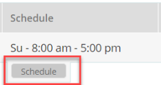
|
|
Scheduling - Click the Schedule button in the Schedule tab. Schedule-SSID window pops-up which displays the options to edit, cancel, or schedule that item. |
|
|
Note:
This option is not available for the XR-320/X2-120.
|

|
1.
|
To specify Schedule SSID time or rule to be active, click the checkboxes for the days that to be active or enable all day is for certain time, instead of few hours or days user can select for All Day. |
|
2.
|
Check the Time On hours that will be enforced, and modify it as needed. |
You cannot apply one filter for two or more scheduled periods, but you can create two filters to achieve that. For example, one filter could block the category Games from 9:00 to 12:00, and another could block them from 13:00 to 18:00. Similarly, you might create two rules for different days—one to block Games Mon-Fri 8:00 to 18:00, and another to block them on Sat. from 8:00 to 12:00.
Note that a policy schedule takes precedence over rule schedules and may override them. Make sure that rules are scheduled within the policy schedule.
|
|
Access Control — To set up special handling when guests connect to this SSID, select Captive Portal, or select None for no special handling. An additional option is AirWatch — select this if you are using AirWatch for mobile device management (this option will be grayed out unless you first set up AirWatch in Add-on Solutions). For details on setting up a captive portal, please see Captive Portal Settings, below. |
|
|
Enable VLANs—allows you to override existing VLAN and subnet schemas by using VLAN tagging. This is recommended for previously unplanned networks, or networks that have grown organically and don't have a consistent set of VLANs across campuses/buildings. After VLANS have been enabled, you may define VLANs and their usage on the SSIDs page, and/or for User Groups (on the Policiespage).Assign VLAN Tags to APs on the My Networks > AccessPoints tab. |
You can schedule the SSID to be on (available)onlyatspecifieddaysandtimes and be off the rest of the time. See Scheduling under SSID.
LEDs
|
|
LEDs — Set this to Yes if you wish to turn off the LEDs on APs for aesthetic reasons. This does not change the operation of the AP in any other way. |
To configure additional settings, see Advanced Settings.
Adavanced Settings
To configure more settings, click Show Advanced link.
|
|
Ethernet — These settings on the AP’s Ethernet ports are usually left at the default settings. Auto Negotiate allows the Access Point to negotiate the best transmission rates automatically. If you disable Auto Negotiate, you must define the Duplex and Speed options manually (otherwise these settings are not available). MTU: the MaximumTransmissionUnitsize. This is the largest packet size (in bytes) that the interface can pass along. Note that for APs such as the XD4-240 with 2.5 GHz ports, the 2.5 GHz speed can only be set via auto-negotiation—thus Auto Negotiate should always be used with these APs. |
|
|
Trunking traffic to Gig2 — This option is not used by most customers. It is used in the special case where you want to isolate the traffic of a particular VLAN (and its associated SSID) by sending it to the Gigabit Ethernet port 2 on profile APs. For example, you might want to isolate Guest trafficfrom enterprise traffic as part of PCI(PaymentCard Industry) compliance. |
To trunk a VLAN to Gig2, select YES and enter the VLAN number. Only one VLAN can be separated in this way—its tagged traffic will use Gig2, while untagged traffic will be sent out of both ports. Gig1 will be used for management traffic and production (enterprise) networks. Note that the VLAN selected here must be in use by at least one SSID. When using this option, you must ensure that the Gig1 and Gig2 ports are connected to different networks, generally on separate switches.You should reboot APs in thisprofile to ensure that these settings will take effect. Also see Limit the DHCP Pool to a single SSID, located above in the DHCP Pool settings.
|
|
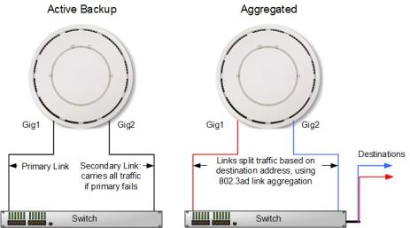
LACP Support for Access Points — This feature is for APs with more than one Ethernet port. Note that to use this feature, the network switch must also support 802.3ad. |
|
n
|
By default, the Gig1 and Gig2 ports function in Active Backup mode (illustrated below). If Gig1 fails, the Access Point automatically uses Gig2 instead—otherwise Gig2 is passive. |
|
n
|
If you enable LACP (Link Aggregation Control Protocol, defined in IEEE 802.3ad), both ports are used and they act as a single logical interface, increasing link speed to the network. A load balancing algorithm balances traffic across the ports. If a port fails, the connection degrades gracefully —the other port still transmits. LACP cannot be used at the same time as Trunking traffic to Gig2 (above). |
|
|
Location Reporting —Set up APs to send data to an analytics server. |
If you are using an analytics server, such as Euclid or the Xirrus Position Server (XPS), use this Location Services section to set up Access Points to send collected data to the server on a regular basis. Cambium Xirrus APs can capture visitor analytics data and upload it to a server, eliminating the need to install a standalone sensor network. This data can be used to provide information such as customer traffic and location, visit duration, and frequency.
When Location Reporting is enabled, the AP collects information about stations, including the station ID and manufacturer, time and length of the visit and related time interval statistics, and signal strength and its related statistics. The AP also sends its own ID so that the server knows where the visitors were detected. Follow the steps in My Network—Floor Plans to create floor plans and set AP locations accurately. XMS sends each AP its positioning information. This allows APs to send better location information and improves integration with analytics servers. Please note that the location reporting setting that enables the display of Stations and Rogues in My Network—Floor Plansis set separately. See Stations and Rogues for details.
To capture and upload location data, set Location Reporting to Yes. Data collected from stations includes only basic device information that is broadcast by Wi-Fi enabled devices. Devices that are only detected are included, as well as those that actually connect to the Access Point.
Enter the following settings.
|
|
What data format do you want to use: If using the Xirrus Position Server, select XPS and just enter the server’s URL in Provide a URL to forward data. For any other type of location server, select Other and fill in the fields below. |
|
|
Provide a URL to forward data: If Location Reporting is enabled, enter the URL of the location/analytics server. If this URL contains the string euclid, then the Access Point knows that data is destined for a Euclid location server. |
|
n
|
For a Euclid analytics server, use the URL that was assigned to you as a customer by Euclid. The Access Point will send JSON-formatted messages in the form required by Euclid via HTTPS. |
|
n
|
For any other location analytics server, enter its URL. The Access Point will send JSON-formatted messages in the form described in the Cambium Xirrus Wireless Access Point User’s Guide (in Appendix B, see “Location Service Data Formats”). |
|
|
Forwarding Period: Specify how often data is to be sent to the server, in seconds. |
|
|
Enable per radio data: Choose Yes to enable the collection and upload of visitor Analytics data on a per-radio basis. APs can then send multiple data points for a station—data is sent for each AP radio that sees a probe request from the station. Choose No to send data on a per-AP basis. |
|
|
Enable MAC Address hashing: Choose Yes to enable encryption of data sent to the location server. No sends data to the location server unencrypted. If you enable hashing, select an encryption Method: |
|
n
|
If MD5 or SHA1 is selected, data is sent with that form of encryption. These satisfy the privacy requirements of the EU General Data Protection Regulation (GDPR). In particular, this assures that client device MAC addresses are encrypted when sent. |
|
n
|
If Customer or Encryption Key is selected, a field is displayed where the key should be entered. Data is sent encrypted using AES with that key. |
Data messages are uploaded via HTTPS, and they are encrypted if you entered a Customer Key. Data is sent as JSON (JavaScript Object Notation) objects. For a complete description of data and formats, see the Cambium Xirrus Wireless Access Point User’s Guide (in Appendix B, see “Location Service Data Formats”).
CaptivePortalSettings
A captive portal supports special handling when guests connect to this SSID, such as redirection to a splash page or login page. If you are using an EasyPass portal for this SSID, this setting is automatically changed to EasyPass Portal for you when you set up the Portal Configuration—SSIDspage under EasyPass, and all portal configuration should be performed on the EasyPass pages. If you use a captive portal that doesn’t use EasyPass, see the splash page, basic login page, and landing page options below.
In SSIDs, when you set Access Control to Captive Portal, the Configure button appears. Click it to set up one of the portal types below. Note that some portals have an Advanced option for entering a Whitelist of websites that users can access without going through the captive portal (see About Whitelists).
|
|
EasyPass Portal—If you have already configured an EasyPass portal on this SSID, then this fiel disautomatically set to EasyPass Portal(see Portal Configuration—SSIDs). All portal configuration is performed under EasyPass. |
|
|
Splash Page—Guests must view and acknowledge this page before proceeding. For example, the splash page can inform the user about the Terms and Conditions for network use before allowing access. By default, the splash page hosting option Host on Cambium Xirrus Access Points (i.e., internal splash page) is selected. A simple editor is provided for designing a locally hosted splash page with text and graphics. Uncheck this option to use a splash page that is on an external server. Click Next and set up the splash page behavior. For an external splash page, enter the External Splash Page URL (the URL of the external web server) and the Redirect Secret (the secret pass phrase defined in the .cgi file that resides on the external web server—not the RADIUS secret). The Session Timeout (optional) specifies how long a client’s association remains valid after a user is disconnected. If a user session is interrupted, say if a mobile device goes into power-save mode or a user closes a laptop lid, the user will not have to reauthenticate unless the length of the disconnection is longer than the timeout. The maximum timeout is 10080 minutes (seven days). Advanced options let you set a Landing Page that users are directed to after the splash page. |
|
|
Basic Login Page—Authenticates users based on account information that you have set up on a RADIUS server. The login page can be hosted on an external server or internally on APs. |
|
n
|
Locally hosted (internal) login page — By default, the option Host onAccess Points is selected. Click Next to specify the RADIUS Authentication server, the type of user authentication, and an optional secondary RADIUS server (it will be used in case the first server does not respond). Set Accounting to Yes if you want to send accounting information to the RADIUS server—optionally, you may specify an Alternate AccountingServer to be used for this purpose. Advanced options let you set a Landing Page that users are directed to after the login page, enter a Whitelist, and for better Security, specify the use of HTTPS for the login page. Click Save to design the login page. A simple editor is provided for designing a locally hosted login page with text and graphics. Click Save & Finish when done. |
|
n
|
Externally hosted login page — Uncheck the Host on Access Points option. Click Next to specify the External Login PageURL and the Redirect Secret (the secret passphrase defined in the .cgi file that resides on the external web server—not the RADIUS secret). Enter the RADIUS Authentication server, the type of user authentication, and an optional secondary RADIUS server (it will be used in case the first server does not respond). See the explanations below for Called- Station-Id Attribute Format and Station MAC Format settings. Advanced options let you set a Landing Page that users are directed to after the login page, and enter a Whitelist. Click Save & Finish when done. |
|
n
|
Called-Station-Id Attribute Format and Station MAC Format — Some RADIUS servers, especially older versions, expect information to be sent to them in a legacy format. These settings are provided for the unusual situation that requires special formatting of specific types of information sent to the RADIUS server. Most users will not need to change these settings. Note that these settings will be ignored for the XR-320 and X2-120. |
|
n
|
Called-Station-Id Attribute Format: Define the format of the Called- Station-Id RADIUS attribute sent from the AP—BSSID: SSID (default) or BSSID. This identifies the AP that is attempting to authenticate a client. BSSID is the MAC address of the radio receiving the client signal. The BSSID: SSID option additionally identifies the SSID to which the client wishes to connect. If your site is using Purple WiFi, you must use Ethernet-MAC, which identifies the AP using its wired network MAC address rather than a particular radio. |
|
n
|
Station MAC Format: Define the format of the Station MAC RADIUS attribute sent from the AP—lower-case or upper-case, hyphenated or not. The default is lower-case, not hyphenated. |
|
|
Landing Page — You can redirect the user to a Landing Page of your choice at the URL that you specify. You might use this to require a user to enter a username and password, and possibly supply a method of payment, before accessing network resources. Click Next to specify the landing page. |
Switches
Switches page allows the user to configure cnMatrix VLANs and Policy Based Automation (PBA) using a Profile or Template. Initially user needs to create a Template or Profile and then click the Switches tile.
User can create Templates and Profiles to configure port settings, making it easy to configure and manage a single switch or 100 of switches.
To configure click on any of the ports. Add/Edit Switch Template Port, window pops up enter the fields to configure/add the Native VLAN (Management VLAN), multiple VLANs, and enable PBA.
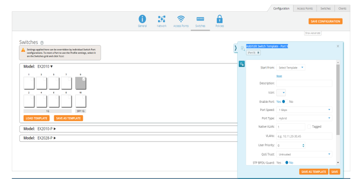
|
|
Enable Port - Select Yes to enable the port, which is a combination of interface type and interface ID. |
|
|
Port Speed - Set the default is for the switch port to Auto, speed configuration is based on signaling between the port and the connected device. |
|
|
Port Type - Select Access, Hybrid or Trunk. An access port carries traffic for only one VLAN, and has only one VLAN configured on the interface. A trunk port carries traffic for several VLANs at the same time. Hybrid port carries multiple VLANs to pass, and can receive and send multiple VLAN packets. You may have multiple VLANs configured on the interface (up to 8 plus one for the PVID, see below). |
|
|
Native VLAN - The native VLAN ID for an interface. |
|
|
An Access port (or untagged port) is a switch port which carries traffic for only one VLAN. |
|
|
A Trunk port (or tagged port) is a switch port which carries traffic for multiple VLANs. |
|
|
VLANs - Enter the VLANs. |
|
|
User Priority - Enter the user priority value ranging from 0 to 7 a format identified and the Virtual LAN information (VLAN id). |
|
|
QOS Trust on a port is set to be Trusted, the received 802.1/DSCP is considered trustworthy and the frame is allowed with those values. |
|
|
QOS Trust on a port is set to be untrusted for all interfaces where all incoming traffic are mapped to TC 0 and are then subsequently mapped to egress queue 0. |
|
|
STP BPDU Guard - Select Yes to enable the STP BPDU Guard. BPDU Guard feature protects the port from receiving STP BPDUs. If BPDU Guard is enabled, the port is shutdown and the state of the port changes to ErrDis (Error-Disable) state. |
|
|
MTU - The MTU setting enables you to configure the Maximum Transmission Unit (MTU) size for all the frames transmitted and received on all the interfaces in a switch. |
|
|
Enable STP - Select Yes to enable the STP. The STP feature enables you to form a loop free network topology. |
|
|
Enable PBA - Select Yes to enable the PBA. |
|
|
Access Security - Select Yes to enable the Access Security. |
Policies
Policies are sets of conditions, constraints, and settings that allow you to decide what types of network traffic are allowed or blocked on an AP. Each policy includes one or more rules. The policy types, depend upon where the policy is applied. Policy types are listed below, in the order of their priority (i.e., global rules have the highest priority and are applied first).
|
|
Policy Based Automation |
|
|
Global Policy(applies universally)
|
|
|
Personal Wi-Fi SSIDs (each rule applies to all personal SSIDs) |
Layer 2 rules will be enforced beforeLayer 3 rules. There can be multiple policies of the same type, for instance, a Device policy for iPhones and a Device policy for Samsung phones.
|
|
NOTE:
Some value-priced AP models (the XR-320 and the X2-120) don’t support all of the policy features or recognize all of the applications available on larger APs. If a profile has settings for a feature not available on a particular AP, those settings will simply be ignored for that AP.
|
After creating a policy, add one or morerules to it. Thereare two types of rules, plus advanced settings:
|
|
Firewall rules—These are used by the integrated firewall on profile member APs. The AP firewall uses stateful inspection to speed the decision of whether to allow or block (deny) traffic. Rules define whether to pass or block traffic. For a global policy, the AirCleaner is a one-click option that adds a number of predefined filter rules to eliminate a great deal of unnecessary wireless traffic, resulting in improved performance. If you don’t want to use all of these rules, simply delete the unwanted ones. Note that the first Air Cleaner rule, Air-cleaner-mDNS.1, is an “allow” rule that allows devices such as AirPlay, Chromecast, and printers to be discovered. It is placed before the block rules—and it must be left in that position. |
|
|
Application Control rules—These are used for controlling what applications may run on your wireless network, or increasing or decreasing the priority of certain applications. For example, you might raise the priority of VoIP applications, while preventing game applications from running. These rules are not available if you have not purchased the Application Control option. |
|
|
AdvancedSettings for Policies—Use these to apply traffic and station limits on profile member APs. |
A policy may include multiple rules (both firewall and Application Control rules)You may fine tune policies and/or individual rules by scheduling the days and hours during which they apply.
|
|
NOTE:
When stations are connected to a user’s EasyPass Personal Wi-Fi SSID, the AP uses NAT in order to maximize their security. Subsequently, since Layer 2 filters do not cross Layer 3 boundaries, Layer 2 filters used with EasyPass Personal Wi-Fi will not have any effect.
|
Creating a Policy
|
1.
|
Select the desired profile, then open its Policies page. Select a policy type to add by clicking its buttonin the right most column of the page |


|
n
|
Policy Based Automation - To create policies and rules for PBA Under Policy Based Automation, click the “+” button to add a new PBA policy. On the fly-out window, give the policy a name and the click +Add Rule. Select the Detection Method you wish to use and the parameters for your selected method. Then click the Add button. Then finish configuring the policy with your requirements. |
|
n
|
Global  —If you select Global, the policy will apply universally. Note that the Global buttonis no longer displayed after you create the policy, since there can only be one global policy, and you have just created it. —If you select Global, the policy will apply universally. Note that the Global buttonis no longer displayed after you create the policy, since there can only be one global policy, and you have just created it. |
|
n
|
SSID  —Click this, and select the SSID to which the policy will apply. Clients connecting to this SSID will be governed by the rules that you add to this policy. Note that you can schedule the SSID to be active only at specified times. See Step 5 below. —Click this, and select the SSID to which the policy will apply. Clients connecting to this SSID will be governed by the rules that you add to this policy. Note that you can schedule the SSID to be active only at specified times. See Step 5 below. |
|
n
|
Personal SSID  —Click this, and this policy will apply to all Personal Wi-Fi SSIDs created by users for an EasyPass Personal Wi-Fi Portal whose SSID is part of this profile. Clients connecting to Personal Wi-Fi SSIDs will be governed by this policy. Note that the Personal SSID button is no longer displayed after you create the policy, since there can only be one Personal SSID policy, and you have just created it. —Click this, and this policy will apply to all Personal Wi-Fi SSIDs created by users for an EasyPass Personal Wi-Fi Portal whose SSID is part of this profile. Clients connecting to Personal Wi-Fi SSIDs will be governed by this policy. Note that the Personal SSID button is no longer displayed after you create the policy, since there can only be one Personal SSID policy, and you have just created it. |
|
n
|
User Group —Click this to create a policy that applies to a group of users. The group members are entered manually as described in Managing Onboarding Users and Their Devices — or entered automatically if you are authenticating via a RADIUS server, or using one of these portal types: EasyPass Onboarding, Google, or Azure.Group membership for a user is determined by a RADIUS attribute if you are using a RADIUS server for authentication, or by their organization or group membership if authenticating via an EasyPass Google or EasyPass Microsoft Azure portal. Thus, you can create policies for groups of users that are defined in EasyPass Onboarding, Google/Azure, or on a RADIUS server. —Click this to create a policy that applies to a group of users. The group members are entered manually as described in Managing Onboarding Users and Their Devices — or entered automatically if you are authenticating via a RADIUS server, or using one of these portal types: EasyPass Onboarding, Google, or Azure.Group membership for a user is determined by a RADIUS attribute if you are using a RADIUS server for authentication, or by their organization or group membership if authenticating via an EasyPass Google or EasyPass Microsoft Azure portal. Thus, you can create policies for groups of users that are defined in EasyPass Onboarding, Google/Azure, or on a RADIUS server. |
Enter the name of this policy in UserGroup (this name is only used to identify the policy).
If you are using an external RADIUS server for user accounts and authentication, enter the RADIUS Attribute value that you use on the server to identify users belonging to this group. Note that the RADIUS server location is specified in the SSID (see SSIDs > Authentication, or for certain captive portal options see SSIDs > Access Control).
If you are using an EasyPass Onboarding portal, set RADIUS Attribute/EasyPass Group to the Group that you entered in the portal.
If you are using an EasyPass Google or EasyPass Microsoft Azure portal, set RADIUS Attribute/EasyPass Group to the Google Apps Organization or Microsoft Azure group that identifies this user group.
When a user is authenticated, the user’s Google organization, Azure group ,onboarding group, or RADIUS Attribute value is sent back, depending on what type of authentication you are using. If this matches the RADIUS Attribute/EasyPassGroup value that you set for a User Group policy, the user is a member of that group and the policy will be applied to the user. For a Google portal, XMS will attempt to apply the most specific organization-to-group match. For example, if a user’s organization structure is DistrictA/SchoolA/Students, then XMS will match a User Group whose EasyPass Group value is Students. If the user is in the organization structure as “/” (root), then there will be no match and the user will not be a member of a user group.
|
n
|
Device  — Click this, and select a DeviceClass to which the policy will apply. Device Class is a general category of device, such as Tablet, Desktop, Phone, or even an Appliance or Car. Optionally, use Device Type to further specify the device, for example, iPhone or Samsung. Note that the XR-320 and X2-120 do not allow you to specify a Device Type. Note that you can also createfirewall rules for an SSID that will apply to a particular device class or type. — Click this, and select a DeviceClass to which the policy will apply. Device Class is a general category of device, such as Tablet, Desktop, Phone, or even an Appliance or Car. Optionally, use Device Type to further specify the device, for example, iPhone or Samsung. Note that the XR-320 and X2-120 do not allow you to specify a Device Type. Note that you can also createfirewall rules for an SSID that will apply to a particular device class or type. |
|
2.
|
Add Firewall Rules  to your policy, if desired. (For the global policy, click the Air Cleaner button if you want to add a number of predefined firewall rules to eliminate a great deal of unnecessary wireless traffic.)You may include both firewall rules and Application Control rules (Step 3, below). For each firewall rule, click New Firewall, then fill in the following information (for Advanced options, see Step 4): to your policy, if desired. (For the global policy, click the Air Cleaner button if you want to add a number of predefined firewall rules to eliminate a great deal of unnecessary wireless traffic.)You may include both firewall rules and Application Control rules (Step 3, below). For each firewall rule, click New Firewall, then fill in the following information (for Advanced options, see Step 4): |
|
n
|
Name: You may enter a descriptive name in this field, or allow XMS- Cloud to automatically create a descriptive name. |
|
n
|
Enable: You may use this field to enable or disable this rule. If you want to stop enforcing a rule temporarily and then resume using it is more convenient to disable and then re-enable it than to delete the rule and then re-enter it. |
|
n
|
Action: Choose whether this rule will be an Allow filter or a Block filter. For an Allow filter, then any traffic that meets the filter criteria will be allowed. For a Block filter, any traffic that meets the filter criteria will be blocked. Note that Advanced Options (Step 4) are only available for “Allow” rules. |
|
n
|
Layer: Select network layer 2 or 3 for operation of this filter. |
|
n
|
Protocol: Choose a specific filter protocol from the pull-down list, or choose any to instruct the Access Point to apply the rule to all protocols. |
|
n
|
Port: From the pull-down list, choose the port type for this filter, or you may choose ANY to instruct the Access Point to apply the filter to any port, or choose Numeric and enter a range of port numbers. |
|
n
|
Source: You may specify a source address to match as a filter criterion. First select the desired type of address (or other attribute) to match: IP Address or VLANID (or MAC Address, if you set Layer to 2 above). Then specify the value to match in the fields that are displayed below it. Choose ANY to use any source address. Check Inverse to match any address except for the specified source. For an IP Address, you must specify a (subnet) Mask. For a MAC Address, you must specify a Mask. Note that the MAC Address Mask operates in the same way as an IP subnet mask: the non-zero portion at the beginning of the Mask specifies the part of the MAC Address that the firewall considers when determining a match, while the rest of the MAC Address is ignored. This may be different from the way some other vendors use a MAC Address Mask. Note that for an SSID policy, you may select a Device Type and optionally a Device Class as the Source and/or as the Destination. |
|
n
|
Destination: You may specify a destinationaddress to match as a filter criterion. Enter the settings as specified above for Source. |
|
n
|
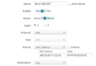
In the example above, the rule named Block ABCDEF disallows traffic that meets its criteria. Layer 2 is selected,which allows traffic to be selected by MAC address. The source is set to examine MAC addresses, and the mask (FF:FF:FF:00:00:00) specifies that only the first three octets of the address should be considered. In the example, this rule will block traffic originating from devices whose MAC address starts with AB:CD:EF. If you select the Inverse option, this rule will apply to traffic that does not originate from a device whose MAC address starts with AB:CD:EF. Note that you can use the FF:FF:FF:00:00:00 mask to select an OUI of a particular device manufacturer. |
|
3.
|
Add Application Control Rules to your policy, if desired. For networks running releases prior to AOS 8.5.6, the option to create these rules is only displayed if you purchased Application Control licenses for any of your APs. For each rule, click New Application Control, then fill in the following information (for Advanced options, see Step 4): |
|
n
|
Name: You may enter a descriptive name in this field, or allow XMS- Cloud to automatically create a descriptive name. |
|
n
|
Enable: You may use this field to enable or disable this rule. If you want to stop enforcing a rule temporarily and then resume using it, it is more convenient to disable and then re-enable it than to delete the rule and then re-enter it. |
|
n
|
Action: Choose whether this rule will be an Allow filter or a Block filter. For an Allow filter, any traffic that meets the filter criteria will be allowed. For a Block filter, any traffic that meets the filter criteria will be blocked. Note that Advanced Options (Step 4) are only available for “Allow” rules. |
|
n
|
Category/Application: This drop-down list displays applications, organized by a category heading followed by applications of that type . For example, select the heading All Games Apps to apply this policy to all games. Or select one of the games listed below the heading, Battle.net for example, to create a rule for just one game application. At the top of the drop-down list there is a search field that will list any application whose name includes the string entered in the field. Note that for the XR-320 and X2-120, a smaller set of applications are available than for larger APs. |
Advanced Settings, Scheduling, Editing, and Precedence for Policies
|
4.
|
Show Advanced—These options allow you to set traffic priority, and traffic and client limits. Which options are offered depends on the type of policy and/or rule. Since QoS, DSCP, and traffic limits manage traffic handling, they only apply to entire policies or to Allow rules. They do not apply to Block rules, because when criteria are met on those rules, no traffic is passed. |
|
n
|
Default QoS: Set packets ingressing from the wired network that match the filter criteria to this QoS level (0 to 3) before sending them out on the wireless network. Select the level from the pull-down list. Level 0 has the lowest priority; level 3 has the highest priority. By default, this field is blank and the filter does not modify QoS level. This is very useful for increasing the priority of business-critical applications, while decreasing the priority of undesirable traffic. For example, you might increase the priority of WebEx, and decrease the priority of games. |
|
n
|
DSCP (Differentiated Services Code Point or DiffServ—DSCP): Set packets ingressing from the wireless network that match the filter criteria to this DSCP level (0 to 63) before sending them out on the wired network. Select the level from the pull-down list. Level 0 has the lowest priority; level 63 has the highest priority. By default, this field is blank and the filter does not modify DSCP level. |
|
n
|
Limit Traffic: Instead of simply allowing the specified traffic type, you may cap the amount of traffic allowed that matches this filter. You may set limits on the total of this type of traffic on this SSID for the AP, and/or per station. Select the units for the limit: Kbps or packets per second (pps). Then enter the limit quantity in the field to the left. |
|
n
|
Client Count Limit: You may cap the number of clients who can connect to an AP under a policy. For an SSID policy, you may cap the number of clients on an AP who may connect to this SSID. For a Personal SSID policy, you may cap the total number of clients on an AP who may connect to all Personal SSIDs. For a device policy, you may cap the number of clients who may connect to an AP from this kind of device. For a user group policy, you may cap the number of group members who may connect to this AP. For a global policy, you may cap the total number of clients who may connect to this AP. |
|
n
|
Station-to-Station Traffic: This setting, only available for the Global policy and SSID policies, blocks or allows traffic between stations. Used in the Global policy, it applies to all profile member APs. Used in an SSID policy, it applies to all clients using that SSID.(Note that in order to filter by SSID, you must set Default Firmware to Technology in Firmware Upgrades.) |
|
n
|
Content Filtering: This setting is only available for SSID policies, and it is enabled on a per-SSID basis. It is used to integrate with a DNS- based content filtering solution to protect your network and users, and to enforce organization-wide restrictions on web sites that may be accessed. Before you can enable this setting, you must enter the IP address of the server as explained in Content Filtering (under Settings). |
|
|
NOTE:
Layer 2 policy rules will be enforced before Layer 3 rules.
|
|
5.
|
Move Up/Down: Rules are applied in the order in which they are displayed on the page, with rules on the top applied first. Click the menu  button (dots) to the right of a rule to show the move button button (dots) to the right of a rule to show the move button  . Click the rule’s move button and drag the rule to the desired location within the current policy. It cannot be moved to a different policy, and Layer 3 rules always have to stay below Layer 2 rules. Note that policies cannot be moved. . Click the rule’s move button and drag the rule to the desired location within the current policy. It cannot be moved to a different policy, and Layer 3 rules always have to stay below Layer 2 rules. Note that policies cannot be moved. |
Optimization
Click the Show Advanced button below the Admin button to display this page. Use it for the following advanced features:
|
|
Client Optimizations — Optimize connections for signal strength and speed. |
|
|
RF Optimizations — Optimize connections for signal strength and speed. |
|
|
Traffic Optimizations — Optimize the handling of multicast traffic to reduce the amount of unneeded wireless traffic. |
|
|
CLI Snippet - Optimize device configuration via CLI commands. |
Client Optimizations
|
|
Roaming optimizes the speed of roaming from one AP to another as a client moves from the reach of one AP to another. |
|
|
Load Balancing groups non-802.11ac clients on some radios while keeping 802.11ac clients together on other radios. This optimizes 802.11ac performance, since faster clients are not slowed down by older, slower clients. |
RF Optimizations
|
|
NOTE:
This page manages wireless radio optimizations. If you wish to manage basic wireless settings for AP radios, select My Network in the menu bar at the top, then select the APs tab. Hover over an AP, click the Details button , and then click the Radios button  . .
|
|
|
MU-MIMO — This stands for the Multiple-User form of Multiple-Input Multiple-Output wireless communication, which is available only on Wave2 802.11ac and later APs. This can help the AP be more efficient with MU-MIMO enabled clients. For example, Wave2 radios have 4 antennas each. The mix of client devices connecting to the AP is likely to average fewer antennas. If MU-MIMO is enabled, then the AP radio could, for example, communicate concurrently with two clients that each have 2- antenna radios with MU-MIMO capability. |
|
|
Beamforming — Beamforming is used for directional signal transmission or reception, and Cambium Xirrus offers it only on Wave2 802.11ac and later APs. This method results in an increased range for devices supporting beamforming. The Cambium Xirrus AP product family supports beamforming only for 802.11ac beamforming capable clients. |
|
|
802.11b — This is an older and much slower wireless mode. When 802.11b devices connect to an AP radio, they severely reduce the radio’s throughput since .11b transmissions are slower and consequently tie up the radio for relatively long intervals. Prohibiting .11b connections for profile member APs will increase wireless network throughput. Note that older devices using 802.11b will be unable to connect to this profile's member APs. |
EasyPass
About EasyPass
EasyPass Access Services enable you to easily provide secure and controlled access to users and visitors on your Wi-Fi network.
Guest Access Portal types:
|
|
EasyPass Guest Self-registration—Users (for example, parents visiting a school) sign themselves up for an account using an online form. If desired, you may set up the portal to require approval by company personnel. |
|
|
EasyPass Guest Ambassador registration—This requires guest accounts (for example, for visitors to a company) to be registered by an employee “sponsor”, using XMS-Cloud’s tools. |
|
|
EasyPass Guest One Click Access—All guests have access after agreeing to terms of use without an account needing to be created. |
|
|
Vouchers—These allow you to generate temporary accounts in bulk, which you can then hand out to visitors. |
Employee/Student Access Portal types:
|
|
Google or Microsoft Azure (Office 365) Login—Users log in using their single sign-on credentials. |
|
|
Onboarding—You can create accounts with unique pre-shared keys that allow Bring Your Own Device (BYOD) users to register their own devices, including printers. For example, this is very useful for employees of an enterprise or for students enrolled in a school or living in a dorm. |
|
|
EasyPass Personal Wi-Fi—Users (for example, guests staying at a hotel for a few nights) sign themselves up to create a custom, secure SSID. If they give the SSID the same name and passkey that their wireless network at home uses, then all of their devices will automatically connect to it! |
|
|
Combine Portals on One SSID reduces the number of SSIDs in your network, simplifying management. |
Additional EasyPass access features include:
|
|
Support for multiple simultaneous portals—For example, you might have a portal for Contractors that requires company approval but has guest accounts that do not expire, and a portal for Visitors whose accounts do not require approval, but expire daily. |
|
|
Email/SMS login notification—Notification may be set up via email or via SMS texts to a mobile phone. |
|
|
Non-IT guest administration—Guest accounts may be administered easily by non-IT staff such as a receptionist. |
|
|
Integrated WYSIWYG editor—A simple editor provides a rich set of options for creating a custom user interaction pages, such as splash and login pages. |
Create an EasyPass Portal
You may create multiple portals and define which SSIDs offer access via each portal.
Click EasyPass on the menu bar, then click  . Select one of the portal types listed below, then enter a unique Portal Name. You may also enter an optional Description of the purpose and setup of this portal for your later reference. You will select the SSIDs that offer this portal later, in the SSIDs tab (see Portal Configuration—SSIDs).
Select the portal type:
|
|
EasyPass Guest: Self-Registration — A sign-up page is displayed to guests, allowing them to create their own account, with or without requiring guests to be sponsored by a company employee. |
|
|
EasyPass Guest: Guest Ambassador — Guest accounts must be entered in advance by a company employee, such as a receptionist. |
|
|
EasyPass Guest: One Click Access — A welcome page is displayed to guests that simply requires them to accept the terms of service (if any) before providing access. No advance setup of an account by an ambassador, voucher, or self-registration is required. |
|
|
EasyPass Voucher — You create guest vouchers in bulk, which may then be handed out to guests to allow them temporary access. |
|
|
EasyPass Google or Microsoft Azure Login — A sign-in page is displayed to guests, requesting their Google or Azure (Office 365) credentials. You may restrict access to users in specific domains or groups. |
|
|
EasyPass Onboarding — This facilitates “Bring Your Own Device (BYOD)” usage. You create user accounts in advance, and a user can register a number of devices simply by connecting to the wireless network. |
|
|
EasyPass Personal Wi-Fi — You create a sign-up page for guests, allowing them to create their own temporary SSID. |
|
|
Combine Portals on One SSID—select two previously defined portals to be combined. See Combine Portals on One SSID for more information. |
Use the following steps to set up your portal:
|
2.
|
Next, use the Portal Configuration — Look & Feel tab to customize the pages and emails that guests will see for registration, logging in, upon granting of access, for setting up their Personal SSID, etc. |
|
4.
|
When configuration is complete, see Managing Guests to view and manage guest accounts, or to add accounts. |
Portal Configuration—General
Settings are presented based on the portal type that you selected:
Self-Registration
Change the following settings as needed.
|
|
Language — Change the language to be used for guest interactions, if other than English. |
|
|
Session Expiration — This is how long the session (registered account) created by this guest registration will continue to allow Wi-Fi access. Once the account is expired, the guest will need to register again. This is different fro m the Session Timeout described below. Note that expiration times of 1 day or 1 month will expire at the same time of day that the user account was granted, i.e., 1 day is 24 hours. End of Day or End of Week expire at midnight on the selected day. Use the Custom option to specify the session duration in terms of days, hours, and minutes. |
|
|
Session Timeout — This is provided to keep users from having to re-log in too often if the user’s Wi-Fi connection terminates. For example, suppose a guest registers and then later leaves the premises for lunch. If the timeout has been set to 2 hours then the user will not have to log in again upon returning (unless it’s a really long lunch). If a guest’s connection does timeout before the session expiration, the guest will be able to log in again with the same user name and password. The maximum timeout is 60 days. If Session Timeout is disabled, then the user will need to log in again each time a wireless connection is re-established. |
|
|
Require Sponsor — If this is set to No, then the user will automatically be sent a password for access to your wireless network. |
If you wish to require sponsorship (authorization) by someone at your organization before the guest is allowed to access the Wi-Fi, set this to Yes, and select the Sponsor Type:
|
n
|
Manual Confirmation — A sponsor must confirm the guest before access to Wi-Fi is allowed (as described in Steps a to d below). |
|
n
|
Auto-Confirmation — A guest will not have to wait for an emailed confirmation from the sponsor before being granted access to the Wi-Fi network, if the guest enters a valid sponsor email. |
|
n
|
Sponsors — Enter the email addresses of one or more personnel who will be emailed a notification of self-registered guests. These personnel do not need to be IT staff. For example, you might choose to have a receptionist approve guest registrations. If you selected Manual Confirmation, one of the sponsors must approve the new guest registration before the guest receives a password. |
Guest registration proceeds as follows if you have selected Require Sponsor and Manual Confirmation:
|
a.
|
The guest registers at your portal registration page (which you will set up later at Portal Configuration—Look & Feel). The guest enters name, email address, mobile number (dashes or periods are optional), country (for mobile carrier), and mobile carrier. The guest must enter the email address of a sponsor. |
|
b.
|
The sponsor email address must match one of the email addresses that you have entered in the Sponsors list. If it doesn't match then no email is sent. For security reasons, the guest will not be notified that there is an error. |
|
c.
|
The sponsor at your organization receives an email from Cambium Xirrus and follows the instructions to approve the guest. |
|
d.
|
The guest receives an email with a password for logging in. If notification by text message has been requested in your portal settings or by the guest, they will receive login credentials by both email and SMS. Note that if all providers have been disabled (see Provider Management), the guest will not see the option to “Receive password via text message in addition to email.” |
|
|
Require Authentication to Connect — If this is set to Yes, then users will be required to enter login credentials the first time they connect. This is useful if you are providing guest access and would like to be sure that guests are entering valid emails and/or phone numbers. After registration, guests are asked to check their email/SMS for login credentials and are redirected to a login screen. After entering their credentials, guests get access to the network. XMS-Cloud generates the credentials automatically and sends them in an email or text message, and also verifies the credentials when guests enter them. Note that this option is only available if Require Sponsor is set to No. |
|
|
Landing — After completing the registration process and being granted access, guests will be directed to this web page. You may wish to enter your organization’s home page here. |
|
|
Whitelist — Set this to Yes to specify Internet destinations that clients can access without first having to login. See About Whitelists for details. |
|
|
Quiet Client Tolerance — Battery powered phones and laptops often conserve battery life by turning off their Wi-Fi radios. When the client “goes quiet” the AP no longer sees it, and the AP assumes the client has disconnected. This setting allows clients to be offline for the specified time before they are considered to have disconnected. We recommend changing the default value (1 minute) only if client sessions appear to be timing out more frequently than the Session Timeout value. |
Proceed to Portal Configuration—Look & Feel and Portal Configuration — SSIDs to complete portal configuration.
Guest Ambassador
Ambassador Portal Settings
For a Guest Ambassador portal, accounts must be manually created for each guest. Note that guests do not have an online method to request an account. Change the settings for Language, Session Expiration, Session Timeout, and Landing as described above for Self-Registration. Advanced settings for Whitelist and Quiet Client Tolerance are also available, as for Self-Registration.
Proceed to Portal Configuration—Look & Feel and Portal Configuration —SSIDs to complete portal configuration. Then click the Guests tab to start creating guest accounts as described below. You may use the Guest Lookup search field to list existing guests whose name or email contain a particular string.
Adding Guest Accounts
For each new guest account, click  . You must enter the following:
|
|
Guest Name — The guest must enter this as their user name to log in on your portal. |
|
|
Email — The Guest Name and the password (automatically created by XMS-Cloud) will be sent to the guest at this email address. |
You may also enter the following optional settings:
|
|
Receive password via text message in addition to email — If you select this option, the guest name and password are also sent to the guest's Mobile phone via SMS text message. (Note that if all providers have been disabled in Provider Management, this option is not offered. ) Select the home country of the guest’s mobile phone provider, then enter the phone number without the country prefix. |
|
|
Guest’s Company — You may use this optional field for your record keeping. |
|
|
Note — This optional text is displayed in the list of guest entries on this tab, for your reference. It is not sent to the guest. |
When you are done entering information for this guest, click  . XMS-Cloud will display the guest name, the assigned password, and the email address to which it has been sent. The new guest account will be added to the Guests list on the Guests tab. Hover over a Guest Name for options to edit the entry, send a new password, disable (or re-enable) Wi-Fi access for the guest, or delete the entry. See also, Managing Guests.
One Click Access
For a One Click portal, no self-registration or pre-registration is required. No login is required, other than any authentication required by the portal’s SSID. This is a simple portal that offers access to anyone for a specified length of time.
Enter the following settings:
|
|
Session Expiration — This is how long this session will continue to allow Wi-Fi access. Once the session has expired, an optional lockout time (below) may restrict the ability to create a new session. Select Forever if the session should not expire. Note that expiration times of 1 day or 1 month will expire at the same time of day that the user account was granted, i.e., 1 day is 24 hours. End of Day or End of Week expire at midnight on the selected day. Use the Custom option to specify the session duration in terms of days, hours, and minutes. |
|
|
Session Lockout — If you want to prevent guests from immediately starting a new session when their current session expires, select Yes. Then select the period of time that guests will be locked out before initiating a new session. The drop-down list choices are the same as for Session Expiration. Select Forever if the guest will not be granted access again, i.e., access for a device is limited to one time. |
|
|
Landing — Guests will be directed to this web page. You may wish to enter your organization’s home page here. |
|
|
Advanced settings for Whitelist and Quiet Client Tolerance are also available, as for Self-Registration. |
Proceed to Portal Configuration—Look & Feel and Portal Configuration— SSIDs to complete portal configuration.
One Click Guests
Click the Guests tab to view the One Click Access portal’s guest sessions, identified by the guest device MAC address. Each session’s Activation (start) and Expiration time are shown.
EasyPass Onboarding
Onboarding is the process of registering multiple Wi-Fi access devices per user. It is intended to be used by members of your organization, rather than by guests. For example, a student at a school or an employee at a company may have a laptop, a mobile phone, a printer, and an iPod that they wish to connect to Wi-Fi. EasyPass Onboarding enables Bring Your Own Device (BYOD) by allowing these devices to be registered for easy access on subsequent connections, while limiting the number of devices that a single user may have registered at one time. The user may connect via all registered devices concurrently.
EasyPass Onboarding provides a User-Preshared Key (User-PSK) for each account. A user registers a number of devices simply by using the account’s User- PSK to connect to the wireless network from each desired device. If a user tries to exceed the maximum number of devices permitted, a page is displayed to allow devices to be de-registered. This permits new devices to be registered instead.
For an onboarding portal, there are two methods for user registration.
|
|
Self-Onboarding—Clients sign in to an open SSID with their email, Google Apps or Microsoft Azure (Office 365) credentials. They are then given their User-PSK which can be used to connect to a secure SSID. |
|
|
Pre-defined accounts—You must create an account in advance for each user of the portal. You may import a list of users to easily create a large number of accounts. See Managing Onboarding Users and Their Devices, which describes how XMS-Cloud automatically generates User- PSKs for accounts. While creating user accounts, you can also assign users to User Groups that make it easy to apply Policies to all members of a group. Note that for this portal type, users do not have an online method to create or request an account. |
The SSID running the onboarding portal must be secure, using WPA2/ 802.1X with AES encryption, and having authentication set to User-PSK. Assigning an SSID to this type of onboarding portal will automatically configure these settings on the SSID (see Portal Configuration—SSIDs).
Portal Settings for Onboarding
To configure an EasyPass Onboarding portal, change these settings:
|
|
Session Expiration — This is how long the user account will continue to allow Wi-Fi access. Once a user's session (i.e., account) expires, the user will need to be given a new User-PSK and will have to re-register all devices. Note that expiration times of 1 day or 1 month will expire at the same time of day that the user account was granted, i.e., 1 day is 24 hours. End of Day or End of Week expire at midnight on the selected day. Use the Custom option to specify the session duration in terms of days, hours, and minutes. |
|
|
Self-Onboarding — Select the type of onboarding portal. Select Yes for Self-Onboarding or No for Pre-defined accounts, as described above. Note that if you are switching an existing Onboarding portal from using Pre-defined accounts to Self-Onboarding, the SSID previously defined for the portal will be lost. |
|
n
|
For Self-Onboarding, select the SSIDs to be used by the portal (note that there is no Portal Configuration—SSIDs page). These SSIDs must have been previously defined. For Registration SSID, select one or more open SSIDs (an authentication type will be selected below: Google, Azure, or email). The Registration IDs may come from different profiles. Select a different SSID to be the Network SSID—it may come from any profile. It doesn’t matter how the Network SSID is configured—but note that XMS-Cloud will change its settings so that it is a secure SSID that requires the User-PSK for authentication. |
|
n
|
Select the user authentication type. If you select Email, the user enters an email address to which the User-PSK is sent (in the Look & Feel settings, you may also choose to allow texts to be sent). Note that there is no authentication of the client before the USER-PSK is sent, although you may restrict the email domains that are allowed. |
|
n
|
To set up Google or Azure authentication, see EasyPass Google or EasyPass Microsoft Azure for details on the procedure. The User- PSK will be displayed on the user’s screen. Note that Google authentication allows you to restrict access to only allow users within the domains that you choose, while Microsoft Azure allows you to do the same, but for users in selected groups. |
|
|
Maximum Device Registration — to set a limit on the number of devices that can be registered by each user, select Yes and enter the maximum Number of devices. To add another device after reaching the limit, a user must first de-register an existing device via the page described in EasyPass Onboarding Portal Pages. |
|
|
Landing — Users connecting to your network will be directed to this web page, if the registration process requires them to interact with a browser. For example, users will be directed to this page if they go over the device registration limit, or they are asked to log in using RADIUS credentials in a captive portal. You may wish to enter your organization’s home page here. |
|
|
Optional User Authentication — After a user gains access to the wireless network using the assigned password (User-PSK), you may require authentication using RADIUS if you set this to Yes. This provides an extra level of security. For example, if a registered device is stolen, someone attempting to use it will still need to authenticate using RADIUS credentials. Specify the RADIUS server to be used for authentication, including the Shared Secret that APs must use to access the RADIUS server. The RADIUS server may be configured to use CHAP, PAP, or MS- CHAP. |
|
|
Session Timeout — This option only appears if Optional User Authentication is selected. Once a user's session times out, the user will be asked to enter RADIUS credentials again. Note that this is different from Session Expiration, which dictates when the user needs to enter a new User-PSK. Session Timeout is provided to keep users from having to re-log in too often if the user’s Wi-Fi connection terminates. For example, suppose a user connects and then leaves the premises for an hour. If the timeout has been set to 2 hours then the user will not have to log in again upon returning. |
|
|
Whitelist — Set this to Yes to specify Internet destinations that clients can access without first having to log in. See About Whitelists for details. |
Note that onboarding user accounts are described in Managing Onboarding Users and Their Devices.
EasyPass Voucher
Vouchers are designed to allow companies such as fast food outlets to provide customers with temporary access to Wi-Fi on their premises. You create vouchers in bulk, and can then hand them out to customers. You can export the vouchers as a comma-separated values (.csv) file. The .csv file may be imported into your custom application to give out voucher Access Codes, for instance, printed on a purchase receipt.
The SSID running the voucher portal is typically open (unsecured), but it may be secured if you wish. Assigning an SSID to a voucher portal will automatically configure the Access control setting on the SSID to Captive Portal (see Portal Configuration—SSIDs).
After a user connects to the SSID, the AP presents a login page that requests the voucher Access Code. When a valid code has been entered, the user is allowed Wi-Fi access. The user may connect additional devices using the same voucher, as long as the voucher has not expired.
Portal Settings for EasyPass Voucher
To configure an EasyPass voucher portal, configure these settings:
Session Expiration — This is how long the voucher access code will continue to allow Wi-Fi access. Once a voucher expires, the user will need to obtain a new voucher and will have to log in again. For example, if the expiration is two days and the user returns the next day, the access code will still be valid. Note that expiration times of 1 day or 1 month will expire at the same time of day that the user account was granted, i.e., 1 day is 24 hours. End of Day or End of Week expire at midnight on the selected day. Use the Custom option to specify the session duration in terms of days, hours, and minutes.
Maximum Device Registration — To set a limit on the number of devices that can be registered on each voucher, select Yes and enter the maximum Number of devices. Once a user has registered this number of devices, an attempt to associate another device will be denied with a message explaining that the limit has been reached. Note that a device is registered once access has been granted to it by EasyPass, and remains registered even if it is no longer associated to an AP. Both users and administrators can delete registered devices from a voucher to allow new devices to be used. See Managing Vouchers.
Landing — Users connecting to your network will be directed to this web page. You may wish to enter your organization’s home page here.
Session Timeout— Once a user's session times out, the user will be asked to enter the access code again. Note that this is different from Session Expiration, which dictates when the user needs to obtain and enter a new access code. Session Timeout is provided to keep users from having to re-log in too often if the user’s Wi-Fi connection terminates. For example, suppose a user connects and then leaves the premises for an hour. If the timeout has been set to 2 hours then the user will not have to log in again upon returning.
Advanced settings (click the Show Advanced to see these):
|
|
Whitelist — Set this to Yes to specify Internet destinations that clients can access without first having to log in. See About Whitelists for details. |
|
|
Quiet Client Tolerance — Battery powered phones and laptops often conserve battery life by turning off their Wi-Fi radios. When the client “goes quiet” the AP no longer sees it, and the AP assumes the client has disconnected. This setting allows clients to be offline for the specified time before they are considered to have disconnected. We recommend changing the default value (1 minute) only if client sessions appear to be timing out more frequently than the Session Timeout value. |
Generating vouchers is described in Managing Vouchers.
About Whitelists
A Whitelist specifies Internet destinations that clients can access without first having to log in—these web sites bypass the portal. For example, you may wish to add your public web site to the whitelist. To add a web site to the whitelist for this portal, enter it in the provided field, then click Add. You may enter an IP address or a domain name. Up to 32 entries may be created.
Example white list entries:
|
|
Hostname: www.yahoo.com (but not www.yahoo.com/abc/def.html) |
|
|
Wildcards are supported: *.yahoo.com |
|
|
IP address: 121.122.123.124 |
Some typical applications for this feature are:
|
|
to add allowed links to the landing page |
|
|
to add a link to terms of use that may be hosted on another site |
|
|
to allow embedded video on landing page |
Note the following details of the operation of this feature:
|
|
The list is configured on a per-portal basis. |
|
|
When a station that has not yet passed the portal login attempts to access one of the whitelisted addresses, it will be allowed access to that site as many times as requested. |
|
|
The station will still be required to pass through the configured portal flow for all other Internet addresses. |
|
|
The whitelist will work against all traffic -- not just http or https. |
|
|
Indirect access to other web sites is not permitted. For example, if you add www.yahoo.com to the white list, you can see that page, but not all the ads that it attempts to display. |
|
|
The whitelist feature does not cause traffic to be redirected to the whitelist addresses. |
EasyPass Personal Wi-Fi
This type of portal allows guests to set up their own Personal Wi-Fi networks (i.e., Bring Your Own Network), with no intervention required on your part. Users benefit from the ability to connect all of their personal devices to a secure personal Wi-Fi network with significantly less effort.
When users connect to the SSID that you have set up for the EasyPass Personal Wi-Fi portal, they are redirected to a Personal Wi-Fi creation page to specify their own network: they enter a Personal SSID name and password. XMS-Cloud configures this Personal SSID on the single AP that the user is connected to. Users will typically set up the same SSID name and password that they use at home, which their smartphones, tablets, and other personal devices are already configured to connect with automatically. For example, if a school dormitory or a hotel offers EasyPass Personal Wi-Fi, users will be able to set up SSIDs that mimic their home networks. Their devices will automatically connect securely for the duration of the user's stay (until the Personal SSID expires).
Users may create up to twelve Personal SSIDs (smaller AP models support fewer SSIDs). Personal SSIDs created by users may be viewed and managed on the Personal SSIDs tab, as described in “Managing EasyPass Personal Wi-Fi SSIDs”.
Only one SSID per profile may be assigned to the EasyPass Personal Wi-Fi portal. Note that station-to-station traffic blocking is turned off for all profile-member APs. Thus, clients on the same SSID will be able to pass traffic.
|
|
NOTE:
We recommend planning your Wi-Fi network so that there are no more than 30- 60 clients on any radio. The Station Count alert will appear when the number of clients connected to an AP averages more than 30 per radio (see My Network— Alerts). You may set XMS-Cloud to send you a notification if this alert occurs, as described in My Account. You can also set a limit on the maximum number of clients that can connect to Personal SSIDs on an AP (see Advanced Settings, Scheduling, Editing, and Precedence for Policies).
|
Portal Settings for EasyPass Personal Wi-Fi
To configure an EasyPass Personal Wi-Fi portal, change these settings:
|
|
Personal SSID Expiration — This is how long a user’s personal SSID will continue to allow Wi-Fi access after it is created. Select Fixed to specify a calendar date for all personal SSIDs to expire, for example, if they are to expire after a trade show has ended. Select Relative to specify the number of days, hours, and minutes that the personal SSID will be valid. Once a personal SSID expires, it is deleted by default, and a returning user will have to recreate the personal SSID upon returning. Or you may set Allow returning users to re-enable their expired Personal Wi-Fi network with one click to Yes. |
|
|
Set Personal SSID Broadcasting to Yes to have the name of the personal SSID broadcast to all users who are in range of the AP. By default, this is set to No, for additional security and reduced clutter of SSID names. Set this to Yes to make the personal SSID name visible to everyone in range. |
EasyPass Google
This portal lets clients use their Google Apps credentials to get single sign-on (SSO) access to the organization's network. Access may be restricted to users with email addresses in specified domains.
For extra security, Google 2-Step Verification is supported. This is a feature that admins can choose to set up for their Google domains. When a user logs in with
Google, it sends a pin code to the user via text or mobile app. The user must enter the code to complete authentication. Google portals also offer Directory Synchronization, so that if you delete users from the Google directory, their EasyPass access will also be revoked. Revoked users’ active sessions will be terminated (they will not see any message).
Google portals offer the option of restricting access based on the MAC address of the user’s device (known as a MAC ACL—-Access Control List). To restrict access with a MAC ACL, see The EasyPass Google or Azure Access Control Tab (MAC ACL).
|
|
Directory Synchronization — Enabling this gives you the option to grant access only to users in a selected Google Directory Organization, or you may still grant access to all users in the Google directory. It also revokes access to users who have been deleted from the Google directory. See Directory Synchronization for EasyPass Google to set up this feature. |
|
|
Maximum Device Registration — To set a limit on the number of devices that can be registered by each user, select Yes and enter the maximum Number of devices. To add another device after reaching the limit, a user must first de-register an existing device via the Manage Devices page described in EasyPass Google or Microsoft Azure Portal Pages. |
|
|
Login Domains — If this portal is to be restricted only to users whose email addresses are in particular domains, enter them here. For example, to allow access only for email addresses at abccorp.com and xyzcorp.com, enter those domains here. Click the Add button after each addition. If you don’t enter any domains, then only email addresses in the Google domain are allowed. |
|
|
Landing — After completing the registration process and being granted access, guests will be directed to this web page. You may wish to enter your organization’s home page here. |
|
|
Session Timeout — Once a user's session times out, the user will be asked to log in again. Session Timeout is provided to keep users from having to re-log in too often if the user’s Wi-Fi connection terminates. For example, suppose a user connects and then leaves the premises at the end of the day. With the default timeout of 30 days, the user will only have to supply credentials again once a month. |
Directory Synchronization for EasyPass Google
Directory Synchronization offers additional features for Google portals.
|
|
It lets EasyPass automatically remove users as they are removed from your Google Directory. |
|
|
Another option allows you to restrict access so that only a specific subset of users (Organization) in your Google Directory can use the portal, rather than granting access to all directory accounts. |
Set up Directory Synchronization for Google as described below.
|
1.
|
Set Directory Synchronization to Yes. Click the Follow these steps link that appears. Instructions for Configuring Google Apps Domain Directory are displayed (and shown in Step 2 and Step 3, below). These steps tell you how to configure Google Apps (also called G Suite) to permit XMS-Cloud to use the apps necessary to implement Directory Synchronization. |
|
a.
|
Select Security from the list of controls. If you don't see Security listed, select More controls from the gray bar at the bottom of the page, then select Security from the list of controls. |
|
b.
|
Select Advanced settings from the list of options. |
|
c.
|
Select Manage API client access in the Authentication section. |
|
d.
|
In the Client Name field enter (copy and paste) the long string of digits shown in Step d in the Configuring Google Apps Domain Directory window. |
|
e.
|
In the One or More API Scopes field enter (cut and paste) the following strings, separated by a comma: https://www.googleapis.com/auth/admin.directory.orgunit.readonly, https://www.googleapis.com/auth/admin.directory.user.readonly |
|
f.
|
Click the Authorize button. This, together with the steps below, allows XMS-Cloud to use these APIs. |
|
3.
|
Back in XMS-Cloud, click Authorize. |
|
|
On the Google pop-up, authenticate (log in to Google, if you haven’t already) and click Allow to authorize the access by the EasyPass Portal web application. |
|
4.
|
On the portal General tab, click Verify Connection to Google Directory. When prompted, enter a user who has admin privileges for your Google (G Suite) Directory. XMS-Cloud verifies that Directory Synchronization was properly configured, and then informs you that Directory sync is Active. It will also display the email address of the Google Directory Administrator. |
|
5.
|
To allow portal access to all users with Google Directory accounts, set Synchronize with an Organization in the directory to No (this field only appears if your configuration has been verified). Otherwise, to restrict access to only one Organization, set this to Yes and select one of your G Suite Organizations. |
Advanced Settings for EasyPass Google
|
|
Whitelist — Set this to Yes to specify Internet destinations that clients can access without first having to log in. See About Whitelists for details.. |
|
|
Quiet Client Tolerance — Battery powered phones and laptops often conserve battery life by turning off their Wi-Fi radios. When the client “goes quiet” the AP no longer sees it, and the AP assumes the client has disconnected. This setting allows clients to be offline for the specified time before they are considered to have disconnected. We recommend changing the default value (1 minute) only if client sessions appear to be timing out more frequently than the Session Timeout value. |
Proceed to Portal Configuration — Look & Feel and Portal Configuration — SSIDs to complete portal configuration. Note that since authentication is performed by Azure, you do not create any login pages for user interaction, but you can customize a Manage Devices page. Go to the Users tab to view users who have authenticated to the portal.
The EasyPass Google Users Tab
Select the Users tab to display all users who have gained access to the Easypass Google portal at least one time. You can export entries as a comma-separated values (.csv) file in the same way as described in “Export to CSV file”.
To disable a user’s network access, delete the user’s entry on this page.
To view the devices that a user has onboarded, hover over the user’s entry and click the Details button . The slide-out panel lists each device along with its type and MAC address, and allows you to delete devices. You must click the Save button to save any changes made.
Note that accounts do not expire, although users will have to re-enter their credentials if you have enabled Session Timeout.
The EasyPass Google or Azure Access Control Tab (MAC ACL)
This feature allows you to restrict access to this portal so that only user devices with specific MAC addresses can gain access. For example, organizations that issue devices to users, such as schools, would like to allow only those devices to access certain portals. To use this feature, create a list of MAC addresses that are permitted on this portal—usually called a MAC Access Control List (ACL). If there are no entries in the list, then access is not restricted by MAC address.
|
1.
|
Select the desired Google or Azure EasyPass portal, then click the Access Control tab. |
|
2.
|
To add a single device to the list, click New Device. Enter the device MAC address. Use the optional Details field for any notes you’d like to add. |
|
3.
|
To import multiple MAC addresses from a spreadsheet, click Manage Device Data, then click Import. To download a sample .csv file showing the expected format, select Get template from the drop-down list. |
|
4.
|
To export the list, select Export All from the drop down list. This option only appears under Manage Device Data when the list has at least one entry. |
EasyPass Microsoft Azure
Azure portal clients use their Microsoft Azure (Office 365) Active Directory credentials to get single sign-on (SSO) access to the organization's network. Access may be restricted to users in specified Azure groups. If you delete users from Azure, their EasyPass access will also be revoked. Revoked users’ active sessions will be terminated (they will not see any message).
Azure portals allow you to restrict access based on the MAC address of the user’s device (known as a MAC ACL—-Access Control List). To use this feature, see The EasyPass Google or Azure Access Control Tab (MAC ACL).
You must set up Azure to accept and service XMS-Cloud requests for authentication of clients, via one of these two methods.
|
|
Add the Cambium Xirrus EasyPass app to your Azure Active Directory tenant (this requires special Azure privileges). After this, any XMS-Cloud user who is creating a portal can perform the authorization step. This user does not need an Azure account with special privileges. The app will also be used if you configure XMS - Cloud Single Sign-on (SSO) to authenticate users logging in to XMS-Cloud. Proceed as directed in To use the Cambium Xirrus EasyPass app for authorization. |
|
|
You may authorize XMS-Cloud access to Azure separately for each portal. Each time you do this, global admin permission for the Azure Active Directory tenant is required. Proceed as directed in To authorize a portal without the app. |
To use the Cambium Xirrus EasyPass app for authorization
|
1.
|
Click the Follow these steps link to display instructions for installing the app and completing integration with Azure. Click Authorize to go to Azure and start the process. Note that special Azure privileges are required to install an app. |
|
2.
|
Installation of the app may take a few minutes, so please be patient. |
|
3.
|
Still in Azure, open the newly installed Cambium Xirrus EasyPass app. In the Security section, select Permissions. Click the blue box that says Grant admin consent for <your_active_directory>. |
|
4.
|
Back at the EasyPass portal General page, XMS-Cloud will indicate that the integration with Azure was successful. |
To authorize a portal without the app
|
1.
|
Click Authorize. On the Microsoft pop-up, log in as a Microsoft Azure Active Directory user with global admin privileges for this tenant. Click Accept to authorize the EasyPass Portal web application to access the Azure directory. You will be returned to the EasyPass portal General page. |
|
2.
|
Under the Authorize button, XMS-Cloud shows the Azure domain whose users may log in to this portal. Only one Azure domain is permitted per portal. (To allow multiple domains to be handled on the same SSID, see Combine Portals on One SSID.) |
Enter the remainder of the Azure portal settings
|
1.
|
Under the Authorize button, XMS-Cloud shows the Azure domain whose users may log in to this portal. Only one Azure domain is permitted per portal. (To allow multiple domains to be handled on the same SSID, see Combine Portals on One SSID.) |
|
2.
|
If you have set up user groups in your Azure domain, you may restrict access to allow only users belonging to selected groups. Set Would you like to restrict access to specific groups to Yes. Please wait for XMS- Cloud to list the groups defined in the Azure domain—this may take some time. Select a group, click Add. Repeat to add all of the desired groups. |
|
3.
|
Maximum Device Registration — To set a limit on the number of devices that can be registered by each user, select Yes and enter the maximum Number of devices. To add another device after reaching the limit, a user must first de-register an existing device via the Manage Devices page described in EasyPass Google or Microsoft Azure Portal Pages. |
|
4.
|
Landing — After completing the registration process and being granted access, guests will be directed to this web page. You may wish to enter your organization’s home page here. |
|
5.
|
Session Timeout — Once a user's session times out, the user will be asked to log in again. Session Timeout is provided to keep users from having to re-log in too often if the user’s Wi-Fi connection terminates. For example, if a user connects and then leaves the premises for lunch, the session is not terminated. By default for Azure, the Session Timeout is set to 30 days to match typical single sign-on defaults. |
Advanced Settings for Microsoft Azure
Whitelist — Set this to Yes to specify Internet destinations that clients can access without first having to log in. See About Whitelists for details.
Quiet Client Tolerance — Battery powered phones and laptops often conserve battery life by turning off their Wi-Fi radios. When the client “goes quiet” the AP no longer sees it, and the AP assumes the client has disconnected. This setting allows clients to be offline for the specified time before they are considered to have disconnected. We recommend changing the default value (1 minute) only if client sessions appear to be timing out more frequently than the Session Timeout value.
Proceed to Portal Configuration—Look & Feel and Portal Configuration—SSIDs to complete portal configuration. Note that since authentication is performed by Azure, you do not create any login pages for user interaction, but you can customize a Manage Devices page. Go to the Users tab to view users who have authenticated to the portal.
The EasyPass Microsoft Azure Users Tab
Select the Users tab to display all users who have gained access to the EasyPass Microsoft Azure portal at least once. You can export entries as a comma- separated values (.csv) file in the same way as described in “Export to CSV file”.
To disable a user’s network access, delete the user’s entry on this page. The user can re-authenticate unless the user’s device has been blocked (see My Network— Clients).
|

|
Note:
Accounts do not expire, although users will have to re-enter their credentials if you have enabled Session Timeout.
|
To view the devices that a user has onboarded, hover over the user’s entry and click the Details button . The slide-out panel lists each device along with its type and MAC address, and allows you to delete devices. You must click the Save button to save any changes made.
The EasyPass Azure Access Control Tab (MAC ACL)
See The EasyPass Google or Azure Access Control Tab (MAC ACL).
Combine Portals on One SSID
This option offers clients the choice of two portals on one SSID. Use this to reduce the number of SSIDs in your network and simplify management. For example, you can offer two different portal types while having only one open SSID in your wired network. A Welcome Page (example below) allows the client to select one of the two portals, and the client then proceeds to obtain access using that portal.
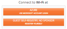
The two portals to be combined must already have been created. Before deployment, they should be completely defined as described in Portal Configuration—General and Portal Configuration—Look & Feel. The settings on those pages will be used for the portals. There is no need to associate the individual portals with SSIDs, since you will specify an SSID for this combined portal in Portal Configuration—SSIDs. However, if SSID values are set for the individual portals, the portals will be offered on the specified SSIDs as well.
Enter the following settings:
|
|
Select the Language to be used for the combined portal interface. |
|
|
Use Portal 1 and Portal 2 to select the portals to be combined. |
The following portal types may be combined:
There is no Users tab for the combined portal. Each client will select one of the two portals, and will appear on that portal’s Users tab for management purposes.
Proceed to Portal Configuration—Look & Feel to create the portal choice page for clients, and then use Portal Configuration—SSIDs to select the SSID for this portal.
Portal Configuration—Look & Feel
Click the Look & Feel tab to customize the web pages and emails used to welcome users and guests and walk them through the steps of obtaining access. You can customize pages and emails by adding a logo, background, and text, enabling terms of use, allowing social media logins, and more. Note that the last section below, How to Customize a Page, describes how to use the page design features.
Once you have completed configuration as described in the sections below, see Portal Configuration—SSIDs to assign SSIDs to your access portal.
Self-Registration Portal Pages
This includes six items that you can customize, including emails and web pages. See How to Customize a Page for details on configuring the fields on these pages.
|
|
Welcome Page — This page appears for first-time guests who have never registered. They must click the Register button to show the Register page. An option to log in is provided for guests who already have a password. |
|
|
Register Page — When first time guests click the Register button on the Welcome page, this page collects their account information. If you have chosen to enable Terms of Use, guests see an “Agree and Register” button, and can display the terms of use that you supply. |
|
|
Success Page — For sponsored portals, this page is displayed to the guest after a successful registration, without needing to login. A password email is also sent to the guest. |
|
|
Password Email — This email is sent to guests after they have successfully registered. It informs them of their automatically generated password. Note that guests are not able to change their own passwords. |
|
|
Login Page — This page appears for returning guests who have a password. If you have chosen to enable Terms of Use, guests see an “Agree and Login” button, and can display the terms of use that you supply. |
|
|
Terms of Use — If you have enabled Terms of Use for this portal, this page appears if guests click a link on the Login or Register page to see the Terms of Use. |
Guest Ambassador Portal Pages
This type of portal only uses two guest pages (an email and a login page), since your organization explicitly creates all guest accounts as described in Managing Guests. See How to Customize a Page for details on configuring the fields on these pages.
|
|
Password Email — This email is sent to a guest after your organization creates an account, and contains the automatically generated password. There is no option to enable Terms of Use for Guest Ambassador portals. You may add any text you like to this email, but the Login Page has no Terms of Use features. Note that guests are not able to change their own passwords. |
|
|
Login Page — This page appears for guests who have a password. |
One Click Portal Pages
This simple portal includes just three pages that you can customize. See How to Customize a Page for details on configuring the fields on these pages.
One-Click Access Page — This page appears for guests. It requires them to click the Agree & Connect button to accept the Terms of Use and receive access. A link is provided to view the terms of use. If you have not selected Enable Terms of Use, then guests simply click a Connect button.
Terms of Use — If you have enabled Terms of Use for this portal, this page appears if guests click the Terms of Use link on the One Click Access page.
Access Expired Page — When the guest’s Session Expiration time is reached, this page is displayed. It informs the guest when access will be allowed again (after the Session Lockout waiting period, if any, has passed).
EasyPass Onboarding Portal Pages
This type of portal only has two user pages, since your organization explicitly creates all user accounts described in Managing Onboarding Users and Their Devices. See How to Customize a Page for details on configuring the fields on this page.
|
|
Login Page — This page is only used if you have enabled Optional User Authentication on the EasyPass Onboarding Portal Pages. The user sees the Login Page when a registered device is connected. This page collects the user’s RADIUS credentials and authenticates the user. If you have chosen to enable Terms of Use, users see an “Agree and Login” button, and can display the terms of use that you supply. |
|
|
Manage Devices Page — This page appears for users who have already registered the maximum number of devices, and are attempting to add another device. It allows a user to de-register devices so that new ones may be registered instead. |
EasyPass Voucher Portal Page
This type of portal only uses one guest page, since your organization explicitly creates all vouchers as described in Managing Vouchers. See How to Customize a Page for details on configuring the fields on this page.
|
|
Login Page — This page appears for all guests who connect to the EasyPass Voucher portal. Note that there is no user ID to be entered - only a password field where the voucher’s Access Code must be entered. |
EasyPass Personal Wi-Fi Portal Pages
This includes five pages that you can customize, including emails and web pages. See How to Customize a Page for details on configuring the fields on these pages.
|
|
Intro Page — This page appears for guests who connect to the SSID that runs the EasyPass Personal Wi-Fi portal. The Intro page informs users that they are about to create a personal, secure Wi-Fi network that will have a limited operating range. They must click the Get Started button to proceed to the Create page. |
|
|
Create Page — Users enter their personal network name and password here. We recommend that they enter the same network name and password that they use at home—this allows their devices to connect automatically using Wi-Fi connection information already saved on their devices for use at home. Users may change the personal network name and password later, if they wish, by accessing the EasyPass Personal Wi- Fi portal SSID. (Note that the information that users enter here is secure and encrypted only if the portal SSID to which they are connected has been configured as a secure SSID.) Click Include a Personal ID Field if you wish to have users identify themselves with additional information such as a room number or membership ID, and this field will be added to the Create page. Then enter a Label to be displayed on this field, such as the text “Room Number”. Click the Required checkbox if the user must |
enter the Personal ID field. (The Personal ID entered by the user is not verified as being valid, but it is displayed on the Personal SSIDs tab for your reference, see “Managing EasyPass Personal Wi-Fi SSIDs”.) An option option to Enable Terms of Use is provided—if selected, this displays a link to a Terms of Use page after the user has filled in the requested personal SSID information.
|
|
Terms of Use — If you have selected Enable Terms of Use for this portal, a link to this page appears on the Create page as described above. Click Define Terms of Use, type or paste your desired user notice information in the dialog box, and click the Save button. Users can click a link to display the terms of use that you supply. |
|
|
Confirmation Page — This page is displayed to the guest after the personal SSID is successfully created. It shows the name of the personal SSID and the time that it was created. |
|
|
Error Page — If users have created too many personal SSIDs on this AP, they will see this error message. Users may create up to twelve Personal SSIDs (smaller AP models support fewer SSIDs). |
EasyPass Google or Microsoft Azure Portal Pages
These portals only have one user page, since the login interface is provided by Google or Azure. See How to Customize a Page for details on configuring the fields on this page.
|
|
Manage Devices Page — This page appears for users who have already registered the maximum number of devices, and are attempting to add another device. It allows a user to de-register devices so that new ones may be registered instead. |
Combined Portal Page (Two-Way Portal)
This type of portal only has one page which asks users which of the two portals they want to use. It then simply directs the user to the selected portal, which you should have already set up. See How to Customize a Page for details on configuring the fields on this page.
|
|
Welcome Page — The link for each of the two portals is identified with two lines—a Title and a Subtitle. Enter the desired text for Portal 1 and Portal 2. |
How to Customize a Page
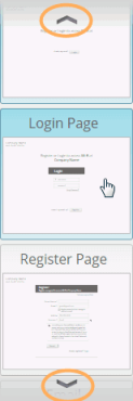
Select the page to be modified from the list of pages offered on the right of the Look & Feel page, as shown in the screenshot at left. A prototype of the selected page will be displayed. Note that you can use the arrows (circled in the screenshot) to scroll up and down to show other pages.
As you make modifications, their effect is shown directly on the page. Here are the modifications that you can make. They apply to all page and portal types unless otherwise indicated.
Company Name — Will appear on the upper left. The font, size, and color cannot be changed.
|
|
Logo — click Select Image. You may select one of the displayed previously uploaded images, or click Upload new image to browse to an image, or click Add external image to specify the image using its URL. Logos may be JPG, GIF, or PNG images with a maximum size of 100x100 pixels. Images larger than 100x100 will be resized. The logo will be displayed on the upper left, with the Company Name to the right of it. |
|
|
Background — This adds a background image to the following portal types: Guest Self-Registration, One Click, Voucher, and Guest Ambassador. To add a background, click Select Image. You may select one of the displayed previously uploaded images, or click Upload new image to browse to an image, or click Add external image to specify the image using its URL. Background images may be JPG, GIF, or PNG images with a maximum size of 1600 x 1000 pixels. Larger images will be resized. The maximum file size for upload is 1 MB. After you select an image, the Fill Screen option appears. If you select this option, the image will be resized to fit the width and height of the screen, else the image will appear centered. Text and dialog boxes will appear on top of the background. Note that the background image will appear in the prototype page types at the right—it appears in all of the page types that will use the background. |
|
|
Color Scheme — Select the color to be used for the main action button (such as Register or Login) on all pages. To select a custom color, choose the rightmost (crosshatched) square while viewing the Welcome page. |
|
|
Require mobile number collection — Whether it is optional for the user to supply a mobile number. |
|
|
Allow sign in with (Login page for Self-Registration portals) — This allows social media sign-in. Check off the options that you wish to allow, such as Facebook or Google. This option only applies to guest self- registration portals that do not require sponsorship. (Note that the Google+ option is no longer offered, since Google is discontinuing this service.) |
|
|
Enable Terms of Use (Self-Registration portals) — If you enable this, the Terms of Use page appears in the list on the right, and its text may be customized by clicking the Define Terms of Use button. A link to the Terms of Use page appears on the Create page for EasyPass Personal Wi- Fi, or the Login and Register pages for Self-Registration portals, and guests agree to the terms when they complete the page. |
|
|
Show data disclosure (Self-Registration portals) — If enabled, this text appears only on the Register page for first time guests. See the Register page for the exact text. The text cannot be changed. |
|
|
Show “Powered by Cambium Xirrus”— Uncheck this option to remove this Cambium Xirrus statement from every page/email. |
|
|
Marketing Opt-in (Self-Registration portals) — Use this if you want to send marketing materials to guests, but you must get their permission first. Check this box and a field appears on the Look & Feel page for entering the text of your request for authorization. The default message is, “I agree to be contacted from time to time via email or SMS with offers and deals.” Edit this text as desired. The opt-in message appears with a check box on the guest’s Register page, and is enabled by default (i.e., the guest must opt out). |
|
|
Add Text — This field, located under the display of the prototype page, allows you to type in custom text to add to the current type of guest page or email. This text is not added to other page types—if you want the same text on each page, you must enter it for each page. Your text is displayed in slightly different locations for different types of page. As you type into the field, you will see the text appear on the prototype page. |
Portal Configuration—SSIDs
|
|
We suggest that you define SSIDs in your Profiles before creating portals. If you have not already created the SSIDs on which you wish to operate portals, please go to SSIDs and create them now. |
|
|
Open the desired portal under EasyPass, select the SSIDs page, and click +Assign SSIDs. Select the SSIDs on which this portal is to be presented and drag them to the right-hand column. (Note that for an EasyPass Personal Wi-Fi portal, only one SSID from each profile may be assigned to the portal.) You may use the drop-down list on the upper left to View All SSIDs, or only view those from a particular Profile. XMS-Cloud will configure the selected SSIDs by setting their Access Control to Captive Portal, if they are not already configured that way. SSID authentication will also be changed to the type expected by the portal. |
A portal may run on multiple SSIDs, i.e., the portal may operate on more than one SSID (except for EasyPass Personal Wi-Fi portals, which may only have one SSID assigned). Each SSID may only have one portal defined on it.
Managing Guests
To configure Self-Registration or Guest Ambassador portal guests manually, or to view and manage guest accounts, click the Guests tab  on the upper right. All guests with accounts are shown in the guest list regardless of the type of portal, whether self-registered or not. The State column shows whether the account is enabled (active), expired, or has been manually disabled. The most recent Activation date for the account is shown. For active accounts, Expiration shows the date that the account will expire. For expired accounts, this shows the most recent expiration date. For more information, see Session Expiration under Self-Registration.
Use of this page is described in the following topics:
Managing Guests—Details
|
2.
|
To make changes to a guest account, hover anywhere over the guest entry to display the available options, as shown below. |
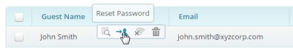
Hover over any button to see a tool-tip showing the button’s function:
|
|
Edit/View Guest Details allows you to edit any field except for the guest email address. If the address is incorrect, you may delete this account and create a new one. |
If the account does not have wireless access, you may Enable Access. If the account does have access enabled, options are provided to Remove Access or Reset & Send Password (this will also extend the expiration of access based on this new activation).
|
|
Reset Password allows you to Reset & Send Password to the guest. The old password is no longer valid and the expiration is extended based on this new activation. This option is only available for active accounts (inactive guests must re-register). |
|
|
Extend Access extends access to this guest for another full session according to the guest’s configured settings. |
|
|
Remove/Enable this guest’s Wi-Fi access — The function of this button changes, depending on whether the guest currently has Wi-Fi access enabled. |
|
|
Delete Guest removes this guest account. |
Export to CSV file
|
1.
|
If you are not already on the guest page, click the Guests tab. |
|
2.
|
To export a list of guest accounts as a .csv (comma-separated values) file suitable for use with Excel and other applications, click the Manage User Data button on the upper right. Select Export All Guests for a spreadsheet with information such as the guest name, activation time, email address, and whether the marketing opt-in was accepted. If you need the MAC addresses of guest devices, in addition to the information usually included, select Export Guest MACs. |
|
3.
|
Most browsers will export the Guests list to a .csv file which you may use as you wish. If you are using Safari, perform the steps below to save the file. |
|
4.
|
Safari opens a new window with the resulting csv data. Right-click in that window. Select Save page as from the drop-down menu. |
|
5.
|
A dialog box appears. Set Export as to a file name with a .csv extension, for example, guest-data.csv. Set Format to Page Source. Click Save. |
Managing Onboarding Users and Their Devices
User accounts for an EasyPass Onboarding Portal must be explicitly added to XMS-Cloud by a user or administrator. Wireless network users cannot register their own accounts. You may add individual user accounts manually, or import an Excel file with a list of accounts. When you add new users to the portal, XMS- Cloud generates a User-Preshared Key for each account (User-PSK). All of a user’s devices gain access and are registered by entering this key. An EasyPass
Onboarding user enters this User-PSK the first time he or she connects to the Cambium Xirrus Wi-Fi network from each device to be registered.
You are responsible for notifying the user about the assigned User-PSK. A list of user accounts may be exported to a .csv file, and you may use this obtain a list of user names and User-PSKs to create user notifications.
If the user attempts to register too many devices (i.e., the Maximum Device Registration value specified on the Configuration-General page has been exceeded—see Portal Settings for Onboarding), the user is notified via the Manage Devices Page (see EasyPass Onboarding Portal Pages). This page allows devices to be de-registered to make room for other devices to be onboarded.
How to Add or Manage Users
|
1.
|
To add users, or to view and manage their accounts, select the Onboarding portal from EasyPass, and then click the Users tab  on the upper right. on the upper right. |
|
2.
|
To add an individual account manually, click +New User. Enter the user’s Name—this name is just for your convenience and is not used by XMS- Cloud or by APs. Enter an Email address and User ID for the account. User ID is the only field that is actually required for an entry. If you wish, you may use the Note field for your own reference information. You can use an email address in either the Name or User ID field if you wish, but XMS-Cloud will not check that the address is valid. You may also optionally specify a Group to which this user belongs by typing the group’s name or selecting an existing group from the drop-down list. You can then create user Group Policies for this group, to easily apply uniform policies to all of its members. If the group name that you entered does not already exist, it will be created. |
Authentication Username (optional) is used if you have enabled Optional User Authentication in Portal Settings for Onboarding. It specifies the RADIUS user name for this account. This adds an extra level of security to the RADIUS authentication by making sure that the user authenticates with the correct account name, rather than using someone else’s RADIUS credentials. If Optional User Authentication is enabled, you may enter a username or leave this field blank for particular entries, as desired.
|
3.
|
To add multiple accounts at one time, prepare a .csv (comma-separated values) file. To download a .csv file that shows the expected format, click Manage User Data, then select Get Template. Your file may have one to seven columns of data—only the UserId column is required. You must use the exact column headers shown for the columns that you include— do not capitalize, use punctuation, or change the spelling. See the example screenshot below. The fields are all the same as described above, with the addition of Passphrase. This optional column specifies the User- PSK for each user account—if you omit this column, XMS automatically generates a User-PSK for each entry. If you include this column, but leave it blank for some of the rows, then only these rows will have their passphrases automatically generated. Click Manage User Data, then select Import Users to read the file and create accounts for all of the users in the spreadsheet. |
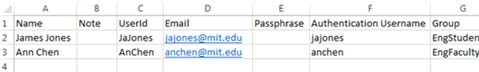
|
4.
|
The new user accounts are included in the list on the Users page. Each entry shows the User-PSK (if you did not enter a passphrase, this is automatically assigned by XMS-Cloud), as well as the Name, User ID, Group, and Note, if any. If you enabled Optional User Authentication in in Portal Settings for Onboarding, the Authentication Username column shows the RADIUS user name assigned to this user account, if any. The Registered Devices column shows the number of devices that have been registered by this user. Hover over an entry to display options for editing, deleting, or generating a new User-PSK. If you use this last option, the user will have to re-register devices, and the old PSK will no longer work. |
|
5.
|
To assign new U-PSKs to some users, select the desired users and click the Regenerate U-PSK button. New or regenerated U-PSKs are not automatically mailed to users, but you can Send All U-PSKs or select some users and just send the current U-PSKs to them. |
|
6.
|
Click Manage User Data, then select Export All Users if you wish to download a .csv file with user accounts, including the User ID and User- PSK for each. See Export to CSV file for more information. |
|
7.
|
To view user information, hover over the user’s entry and click the Details button . The More drop-down menu allows you to delete this |
user entry, or generate a User-PSK (the user will have to re-register devices with the new PSK). To view and manage the devices that a user has onboarded,
|
8.
|
Click the Devices button  on the left of the User Details display. This lists each device along with its type and MAC address, and allows you to delete devices. on the left of the User Details display. This lists each device along with its type and MAC address, and allows you to delete devices. |
|
|
Note:
you must click the Save button to save any changes made to either of the User Details windows.
|
|
9.
|
To Delete entries, Extend Access of existing user or Regenerate User-PSKs for multiple entries, first select the desired entries to make these buttons appear. |
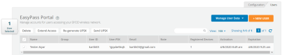
|
10.
|
Extend Access: Allows to extend access of the existing users for another full session accordingly rather than regenerating the User-PSKs. |
Managing Vouchers
All EasyPass Vouchers are shown in this list, regardless of whether they have been used. The Access Code column shows the password for this voucher in clear text. The State column shows whether the access code is Pending (unused), Active (in use), or Expired (used and expired). Active and Expired vouchers show their Activation date—the first date that someone logged in using this Access Code. They also show an Expiration date—when the voucher will expire or has expired.
The Registered Devices column lists the devices (if any) that have been registered on each voucher. You may select a registered device and delete it to revoke its access privilege—if the device is currently connected to an AP, it will be disconnected. If a voucher had the maximum allowed number of devices registered, deleting one will free up a slot for a new device.
How to Manage Vouchers
|
1.
|
To add, view, and manage vouchers, select the EasyPass Vouchers portal from EasyPass, and then click the Vouchers tab  on the upper right. on the upper right. |
|
2.
|
The Voucher list shows your existing vouchers and whether each is in use (Active) or not (Pending). If a voucher is Active, the number of devices using that voucher is shown, along with the time it was activated and when it will expire. To view information about the devices registered to a voucher, hover over the voucher’s entry and click the Details button . Each device is identified by its MAC address and type. You may delete devices as desired. Note that you must click the Save button to save any changes made. |
|
3.
|
To generate a number of new vouchers, click +New Vouchers. Enter the desired number of vouchers, from 1 to 9999. They will appear in the list as Pending. |
|
4.
|
See Export to CSV file if you want to export a list of all vouchers. If an access code has been used, its Activation and Expiration dates are included. Entries with no activation date have not been used yet. |
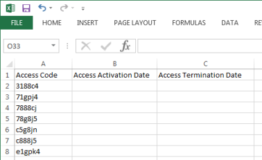
|
5.
|
You may also create vouchers by importing them. For example, you might use this if you want your access codes to have a certain appearance, such as greatcustomer1, greatcustomer2, etc. Prepare a .csv (comma-separated values) file containing no more than 10,000 entries. The file should only have three columns of data with the following column headers in the first row: Access Code, Access Activation Date, and Access Termination Date. You must use these exact column headers—do not change the capitalization, punctuation, or spelling. The columns for Access Activation Date and Access Termination Date should be blank. See the example screenshot above. Click the Import button to read this file and create vouchers for all of the access codes in the spreadsheet. |
|
6.
|
You may reuse existing vouchers rather than generating a new set. Simply re-import existing vouchers (you may export them first if necessary) and choose “overwrite” when prompted. |
Managing EasyPass Personal Wi-Fi SSIDs
All personal SSIDs created by users (as described in EasyPass Personal Wi-Fi) are shown in this list, including those that have expired but have not been deleted due to settings on the General page. The Access Point column shows the AP on which this personal SSID was created. The Profile column shows the profile that the AP belongs to, and where this portal’s SSID is defined. The Status column shows whether the personal SSID is Expired. Active and Expired personal SSIDs show their Created date and their Expiration date. The MAC Address column shows the MAC Address of the device from which this user first connected to the AP and created this Personal SSID. The Personal ID column shows the information that the user entered (if any) when this Personal SSID was created.
Templates
User can create a template to apply bulk configuration for multiple profiles and use it as often as necessary instead of recreating every time for a profile. Once you create the templates, you can either add/edit using the UI and this saves time and eliminate errors
Following templates can be created for profile such as:
Switches
Creating Templates and Profiles to configure port settings, makes it easy to configure and manage a single switch or 100 of switches. User can configure by applying a pre-configured template as shown below:
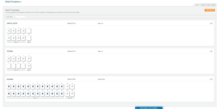
|
1.
|
Navigate to Profiles and click Templates. |
|
2.
|
Click the Switches tab and click the NEW TEMPLATE button. |
|
3.
|
Provide the template a name, select model and click Save. |
User can apply global switch templates at the profile level within the Switch Configuration. These settings can be overridden at the individual switch level if needed.
To apply the template:
|
1.
|
Navigate to the Profiles > Switches tab and select the Switches Model from the list. |
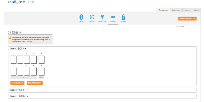
|
3.
|
Load Template window pops up and select the template from the list and click SELECT. |
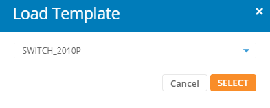
The pre-configured Switch Template will be added. You can make any changes to customize it if necessary. If any changes made to the Switch will not affect the template.
Ports
Creation of Port template which can be used in different profiles, and other enhancements. The ability to create Port templates that can be used across multiple profiles available.
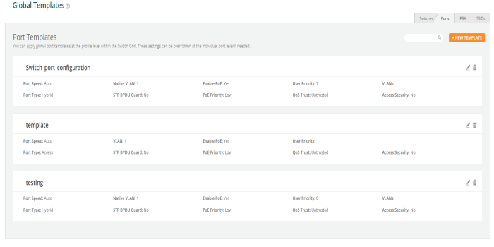
|
1.
|
Navigate to Profiles and click Templates. |
|
2.
|
Click the Ports tab and click the NEW TEMPLATE button. |
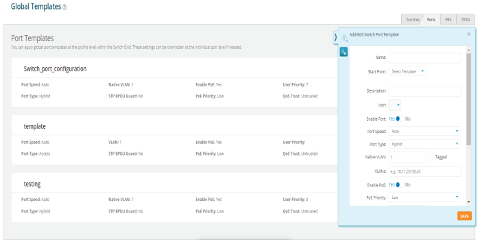
|
3.
|
Provide the template a name and click Save. |
Navigate to the Profiles, click the Switches tab and from the device model select the applicable port and in Start From dropdown select Template. The pre-configured port template will be added. You can make any changes to customize it if necessary. If any changes made to the port will not affect the template.
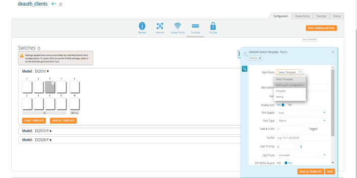
PBA
Creation of PBA templates which can be used in different profiles, and other enhancements. The ability to create PBA templates that can be used across multiple profiles available.
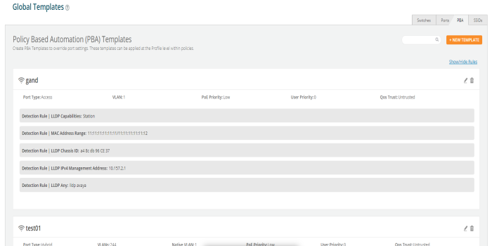
|
1.
|
Navigate to Profiles and click Templates. |
|
2.
|
Click the PBA tab and click the NEW TEMPLATE button. |
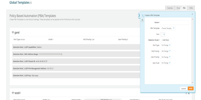
|
3.
|
Provide the template a name and click Save. |
To apply the template, navigate to the Profile, click the Policies tile and click the add new PBA button, and from the PBA Template dropdown select the template. The pre-configured PBA template will be added. You can make any changes to the PBA to customize it if necessary.
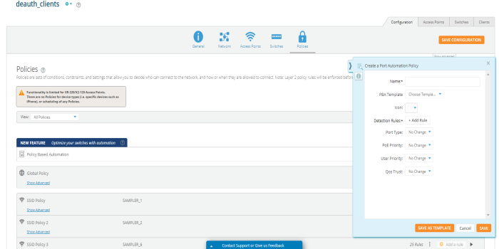
SSIDs
Creation of SSID templates which can be used in different profiles, and other enhancements. The ability to create SSID templates that can be used across multiple profiles available.
To create an SSID template:
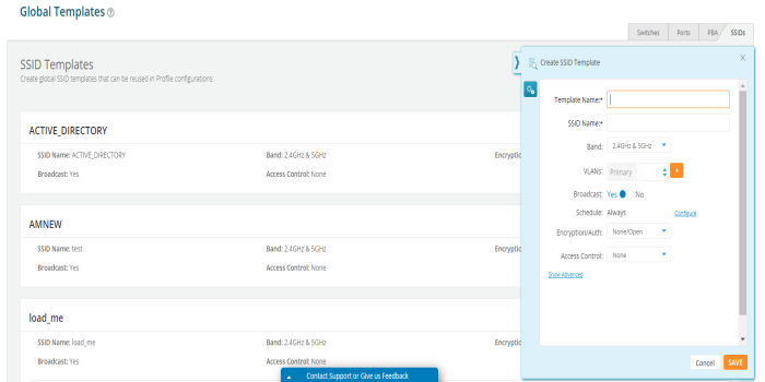
|
1.
|
Navigate to Profiles and click Templates. |
|
2.
|
Click the SSID tab and click the NEW TEMPLATE button. |
|
3.
|
Provide the template a name, cconfigure the SSID and click Save. |
Once the SSID template has been configured, user can add firewall and application control rules. These rules will be enforced whenever this SSID template is used. After the template has been created, can go back to edit or delete the template as needed.
To apply the template, navigate to the Profile, click the Access Points tile and click the NEW SSID button, and from the dropdown select the create from template. The pre-configured SSID template will be added. You can make any changes to the SSID to customize it if necessary. Any changes made to the SSID will not affect the template.
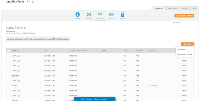
My Network
My Network provides the following tabs for network monitoring and includes tools for troubleshooting.
|
|
My Network—OverviewTab— Provides a map representation of your Cambium Xirrus wireless network, dashboards, and other at-a-glance status and performance displays. |
|
|
My Network—AccessPoints — Shows the APs being managed and their status, and allows you to change some per-APsettings, such as radio settings. |
|
|
My Network—Clients — Shows the wireless clients that have connected to the network, and allows you to block clients. |
|
|
My Network-Alerts — A display of wireless network problems that requireyour attention. |
|
|
My Network—Floor Plans—Locates APs on a floor plan, showswireless coverage as a heat map, and provides AP management options. |
Filters
Most of the pages in My Network offer granular insight into the network by letting you view information for a selected portion of the network. Use the Filter or Profile/Group field on the upper right to choose one of your Profiles, Access Point Groups, or SSIDs. Only data for APs in that portion of the network will be displayed. For example, you might select your Guest SSID to see data usage by visitors.(Note that in order to filter by SSID, you must set Default Firmware to Technology in Firmware Upgrades.) A tab indicates that a filteris in use by displaying the filter icon: . To revert to seeing data for all APs, set Filter back to All AccessPoints. Many pages also have a View field to select the time period to be included in the display.
My Network—Overview Tab
The Overview tab offers a number of different dashboard views for monitoring network status and performance. Select My Network on the top toolbar, then select the Overview tab. A ribbon offers the following choices:
|
|
Dashboard — Create one or moredashboards to provide custom views of the status and performance information that’s important to you for managing the network. See Dashboard for details. |
|
|
Access Points — This page shows the Top Access Points by usage and a graph of Data Throughput for clients. You may add or delete widgets and change the time period displayed. |
|
|
Clients — This page shows the Top Clients by usage and a graph of Data Throughput. You may add or delete widgets and change the time period displayed. |
|
|
Alerts—This page shows the most recent alerts for the network. See My Network-Alerts for more detailed Alert information. |
|
|
Devices — This page summarizes the most common device types and device manufacturers for clients connected to the network over the selected time interval. You may add or delete widgets and change the time period displayed. |
|
|
Applications — This page provides visibility of application usage by users across the wireless network. See Applications for details. |
|
|
Map — The map shows a geographical representation of the network. See Map for details |
To see results for only a portion of the network or for a limited time period, see Filters. Click or hover on areas of Overview pages that are of interest. Many of them drill down to display more detailed information. Use the Full Screen button  , located on the right and below the ribbon, to expand the current display to most of the page. The Exit Full Screen button
 reverts to the standard display. The Dashboard section below describes adding widgets — they can be added on other Overview pages besides dashboards.
Dashboard
Create dashboards to specify customized views of information needed for network management. For example, you can show the Top Applications (by Usage), the Top Clients (by Usage), and list Clients (by Lowest Health Scores) to show clients that have problems or are generating too much traffic. Summaries are available with summaries of the APs that are up, down, or taken out of service. Each of these types of display is called a widget. Choose from a large variety of widgets presenting different data.
To see results for only a portion of the network or for a limited time period, see Filters.
To create a dashboard and add widgets:
|
1.
|
Click the +New button at the right edge of the ribbon to add a custom dashboard to the ribbon. Click its name (e.g., Dashboard1) if you want to change it. Click the icon to the left of the name to select a different icon. |
|
2.
|
In the dashboard, click AddWidget on the upper right to add widgetsto the dashboard. Select widgets with the information that you want included on this dashboard. You can add or delete widgets at any time, so go ahead and try out different ones to see the data that interests you most. Revisit the list of widget types from time to time, as new widgets areoften included in new releases of XMS-Cloud. |
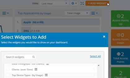
|
n
|
There are two types of widgets in the list that you can choose from. Regular widgets(charts, lists, graphs) are labeled with  . . |
|
n
|
Summary widgets (tiles) are labeled with  . Summaries appear on the right side of the dashboard and display current counts, such as the current number of high alerts, the number of APs down, or the number of clients using 2.4 GHz. Some of these summaries include a link. For example, click Clients on 2.4 GHz to go to the My Network—Clients tab, with filters set to list only the current 2.4 GHz clients. . Summaries appear on the right side of the dashboard and display current counts, such as the current number of high alerts, the number of APs down, or the number of clients using 2.4 GHz. Some of these summaries include a link. For example, click Clients on 2.4 GHz to go to the My Network—Clients tab, with filters set to list only the current 2.4 GHz clients. |
|
3.
|
You can change the time interval for data displayed in each widget. Some widgets can be displayed in different formats (table, bar chart, or pie chart) using the buttons on the lower right. Add more dashboards for different custom views of the network. |
Some dashboard widgets allow you to drill down to view more detailed information. For example, the Applications section below makes extensive use of this. The Clients (by Lowest Health Scores) widget has links for clients experiencing problems — click one to go to its Client Health Score Panel for Troubleshooting.
Another example is the Top Clients (by Usage) widget that allows you to drill down multiple levels to obtain a wealth of detail for troubleshooting a client. This widget shows the clients that have generated the most traffic, and you can choose to select the top clients by time period, and by total usage or upload or download traffic.Click the menu button  to see more display options. For example, the View drop-downlist appears and lets you identifyclients by Hostname, IP Address, etc. Select the display format—list or chart—with the buttons at the
  bottom right.
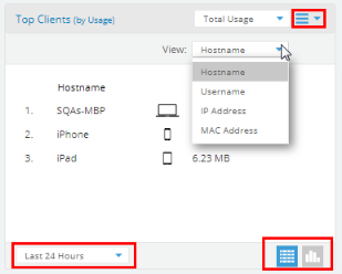
Click a client to show a list of this client’s Top Applications (by Usage). Note that the widget’s title changes to Clients/[this client’s name]. Hover over an application to see a detailed description of that application. Click the Clients link to go back to the original display of Top Clients.
Back at the Top Clients list, hover over a client to see a pop-up of its device type and a short set of additional options.
These options include blocking this client, a shortcut to open the Client Health Score Panel for Troubleshooting, or click the Details link to jump right to the client troubleshooting panel’s  display. See My Network—Clients for more information about clients, blocking, and the troubleshooting features.
Applications
This page summarizes application usage in the wireless network. Access it via the Applications tile in the ribbon on the Overview tab.
In Top Applications by Usage, click on an application to drill down for valuable detailed information, including identifying the major users of the application. Users are identified by device MAC address or by user ID, email, or host name if one of those is available. If the traffic from a particular device is a problem, you can select the device and click its Block link to add its MAC address to a blacklist that blocks wireless network access (for example, you can block access while investigating the problem and possibly adding a filter to address the problem).
Click the Access Points tab to see the top APs handling traffic for the selected application. To return to the list of top applications, click the widget’s title: Applications. You can create Policies to keep network usage focused on productive uses, eliminating risky and non-business-oriented applications discovered in the Applications page, or increasing the priority of mission-critical applications like VoIP and WebEx.
Application Categories by Usage is similar, but it groups applications into categories such as Streaming Media, Networking, and File Transfer. Click on a category to see it broken down to its applications that are generating the most traffic.
Map
The map is a representation of the location of your Cambium Xirrus devices. Colors indicate operational status, and geographical clusters of devices can be grouped for an at-a-glance summary of their status. See My Network—Floor Plans to drill down to views of devices sited in each of your buildings.
|
1.
|
Cambium Xirrus APs are automatically placed when they come online. based on their IP addresses and the location of their Internet Service Provider (ISP). You can drag and drop them to a different location. |
|
2.
|
A side panel lets you move multiple devices, or place them on the map before they have come online. Click > on the upper right to display the panel, then click the Access Points  button. button. |

|
3.
|
All of your APs are listed. Use the filter button to filter the AP list by Model, Profile, IPAddress, or Location. A search string may have a wild card(asterisk) at the end to match any item that beginswith the string you entered.For example, BUILDING1* will match Building1, Building146, etc. Drop-downlists let you select strings to match—forexample, the Model list shows all of the model numbers in your network. button to filter the AP list by Model, Profile, IPAddress, or Location. A search string may have a wild card(asterisk) at the end to match any item that beginswith the string you entered.For example, BUILDING1* will match Building1, Building146, etc. Drop-downlists let you select strings to match—forexample, the Model list shows all of the model numbers in your network. |
|
4.
|
Click the checkboxes of devices to select or deselect them. The checkbox at the top of the column will select or deselect all entries. Drag from anywhere in the list to move the selected devices to wherever you drop them on the map. If they are already on the map, they will be moved to the drop location. |
|
5.
|
Click and drag devices on the map to adjust their locations as needed. |
|
6.
|
Use the Map Tools on the upper left of the map to adjust the display of the desired location. Use the zoom buttons  to zoom in or out, and drag the map to the desired location. To show the location from which you are currently working(i.e.,using your browser to access XMS-Cloud), click the Current Location button to zoom in or out, and drag the map to the desired location. To show the location from which you are currently working(i.e.,using your browser to access XMS-Cloud), click the Current Location button  . Or click . Or click  to enter an address or zip code to display on the map. to enter an address or zip code to display on the map. |
|
7.
|
A sample portion of a zoomed-in map is shown below. |
|
n
|
Each device is indicated by a dot—green for online and red for offline. |
|
n
|
Smaller dots have no clients connected. Larger dots indicate APs with clients, with the number of clients shown to the right of the dot. |
|
n
|
The ring around an AP indicates what bands the clients are connected on—blue for 5 GHz and orange for 2.4 GHz. In fact, this ring indicates what proportion of clients are connected on each band. For example, if an AP has 10 active clients with eight clients at 5GHz and two at 2.4 GHz, then the ring will be blue 80% of the way around, and 20% orange. |
|
8.
|
Hover over a device, or click it when you see the hand symbol, to display detailed information, as shown below: |
|
n
|
If there is a building associated with this location in My Network—Floor Plans, the number of floor plans defined for the building is shown. Buildings and floor plans are automatically associated with the appropriate APs on this map. When you add APs to a floor plan, that plan is associated with the map location that includes those APs. Click the View Building link at the lower right to jump to the associated floor plan. Click the Floor Plan tab  button to see more information about the floor plans at this location. button to see more information about the floor plans at this location. |
|
n
|
The total number of devices is shown along with the number that are online and offline. |
|
n
|
The total number of Active Client Associations on the AP is shown, and the number of clients connected at 5 GHz is shown in blue and the number of clients connected at 2.4 GHz is shown in orange. |
|
9.
|
The clusterfeature displays convenient summaries for groups of APs as shown below. Click the Clustering button  in the Map Tools to create a cluster for each group of APs that are in close proximity. in the Map Tools to create a cluster for each group of APs that are in close proximity. |
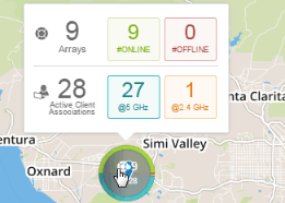
|
|
If clustering is enabled and you do not see any large circles summarizing groups of APs as shown above, zoom out until you do. Clusters are formed based on how close the APs are to each other as you zoom out (if it is not possible to legibly display them individually, they will cluster). If you zoom in far enough, the display will change to individual APs. |
|
|
The cluster is labeled with the count of included APs (top), and the number of active clients (below the AP count). |
|
|
The ring around the cluster may show different statistics: |
|
n
|
If none of the APs in the cluster have active clients, then the green portion of the ring represents the proportion of APs that are online, while the red portion represents the offline portion. |
|
n
|
If any of the APs in the cluster have active clients, then the top half of the ring shows AP status (online percentage in green and offline in red). The bottom half of the ring indicates the bands that clients are connected on—(5 GHz client percentage in blue and 2.4 GHz percentage in orange). |
Hover over a cluster, or click it when you see the hand symbol, to show detailed information:
|
|
The total number of APs in the cluster is shown, and then the number of APs that are online is shown in green, and offline APs are shown in red. |
|
|
The total number of Active Client Associations in the cluster is shown, then the number of clients connected at 5 GHz is shown in blue and the number of clients connected at 2.4 GHz is shown in orange. |
My Network—Access Points
These pages show the APs that are being managed by XMS-Cloud, as well as allowing you to prepare for the installation and management of additional APs.
Before you receive and install APs, follow the instructions in Add APs to XMS- Cloud (The Add/Remove Page) to get the Cloud ready to manage them.
See Managing Access Points (The Monitor Page) to monitor and manage the wireless network.
Add APs to XMS-Cloud (The Add/Remove Page)
Before you power up new APs for the first time, enter (provision) them in the Cloud so that it is prepared to manage them once they are installed (deployed). If you power up an AP before adding it to the Cloud, it will require additional steps to set up the AP to be managed by the Cloud.
Your XMS-Cloud account includes a license to manage a certain maximum number of APs. This number can be increased by purchasing Cloud management for additional APs—and most APs are sold with Cloud management included. The numbers under the Provisioned Access Points title show how many APs have been provisioned and how many APs you are licensed to manage in the Cloud. For example, 10 of 100 indicates that you’ve provisioned 10 APs (including both activated and not-yet-activated units), and that this Cloud license allows provisioning and management of up to 100. A bar chart shows the percentage of licenses that have been used. If there are no more licenses available, you will not be allowed to add APs.
|
1.
|
To add APs to the Cloud, go to My Network, select the Access Points tab, and then select the Add/Remove  page. Add APs in one of these ways: page. Add APs in one of these ways: |
|
a.
|
Click  and enter the Serial Number of an AP. Optionally, you may also enter a Hostname and/or a Location. If you don’t enter a Hostname, then the AP will use its Serial Number as its Hostname. Location is simply descriptive information that you can add to an AP. and enter the Serial Number of an AP. Optionally, you may also enter a Hostname and/or a Location. If you don’t enter a Hostname, then the AP will use its Serial Number as its Hostname. Location is simply descriptive information that you can add to an AP. |
|
b.
|
Click  and select the .csv file sent to you by Cambium Xirrus, containing the serial numbers for the APs that are being shipped to you. The spreadsheet also has columns for hostname and location. If you wish, you can edit the .csv file to add values in these columns for some or all APs, since this is a simple way to get this information into the Cloud. and select the .csv file sent to you by Cambium Xirrus, containing the serial numbers for the APs that are being shipped to you. The spreadsheet also has columns for hostname and location. If you wish, you can edit the .csv file to add values in these columns for some or all APs, since this is a simple way to get this information into the Cloud. |
|
2.
|
Now, install and power up the APs. After they are connected, Cloud automatically establishes communication with them and marks their Status as Deployed. It adds them to the Monitor tab and sets their Status on that page to Activated. See Managing Access Points (The Monitor Page). |
|
|
Note:
All Cambium Xirrus APs running software releases 8.5.6 and higher are automatically licensed for Application Control and all upgrades.
|
Managing Access Points (The Monitor Page)
Select the Access Points page  to show all of the APs known by Xirrus Management System. For each AP, it shows the assigned Profile and DHCP Pool, if these have been configured. It also shows whether the AP is currently Online (i.e., whether the Cloud is able to connect to and manage the AP), and the Expiration Date of its Cloud license. Note that if the license expires, the AP will still connect wireless clients and pass traffic for them, but you cannot make any configuration changes using the Cloud. The Status field shows whether the AP has been Activated for management by the Cloud or not, or whether there is an error condition on the AP—click the information button next to the status for more details. The number of Alerts issued for this AP is shown—click this number to be taken to My Network—Alerts with a filter set to show just the alerts for this AP. If the Alerts column isn’t displayed, the Customizing the Page Display describes how to add it.
The Show drop-down selects whether to display All Devices, only Online APs, or Offline APs (those that have been connected to the network previously, but are not currently connected). You can use the Profile/Group drop-down on the upper right to select one of the Access Point Groups, Profiles, or SSIDs to consider the Profiles, Access Point Groups, or SSIDs to consider.
when displaying results, as described in Filters. You can also use the search field to find particular devices.
This page provides a number of AP management options.
Managing an Individual AP
Select an AP and click the Details  button to view detailed information for the AP and to change per-AP settings such as hostname and specific radio settings. You can view and manage the following:
|
|
Click the General  button to see or edit settings such as IP Address (if the AP’s profile allows static addresses) and Location. button to see or edit settings such as IP Address (if the AP’s profile allows static addresses) and Location. |
|
|
Click the Radios  button to see radio settings. Select a radio to change its settings, such as disabling it, changing its band between 2.4 GHz and 5 GHz, and selecting whether it performs monitoring functions. Click Show Advanced to manage advanced settings such as Channel, RF Transmit and Receive signal strength, Bonding, and Cell Size. button to see radio settings. Select a radio to change its settings, such as disabling it, changing its band between 2.4 GHz and 5 GHz, and selecting whether it performs monitoring functions. Click Show Advanced to manage advanced settings such as Channel, RF Transmit and Receive signal strength, Bonding, and Cell Size. |
|
|
Apart from other Access Point Radios, XV3-8 Access Point radios support Combined/Split mode. |
|
|
By default Radio 1 is set. Click Radio Configuration button to select Split/Combined of Radios 2 & 3  . . |
|
n
|
During combined, only Radio 1 and Radio 2 & 3 Combined are present and configurable. |
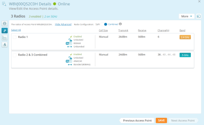
|
n
|
During split, Radio 1, Radio 2, and Radio 3 are present separately and configurable. |
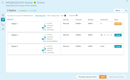
|
|
Click the Statistics button  to see network utilization graphs for the AP. On the lower left, choose whether to display Data Throughput or Total Clients, then select the time window to chart. These charts provide detailed information on usage of the AP that can be used to adjust settings for better utilization and to troubleshoot connection issues. Note that Total Clients is the maximum (peak) number of client stations that associated within each time interval shown on the chart. For example, if 30 clients are shown between 8 AM and 11 AM, then that is the maximum number of clients associated during that interval even though the average number of clients may have been 10. to see network utilization graphs for the AP. On the lower left, choose whether to display Data Throughput or Total Clients, then select the time window to chart. These charts provide detailed information on usage of the AP that can be used to adjust settings for better utilization and to troubleshoot connection issues. Note that Total Clients is the maximum (peak) number of client stations that associated within each time interval shown on the chart. For example, if 30 clients are shown between 8 AM and 11 AM, then that is the maximum number of clients associated during that interval even though the average number of clients may have been 10. |
|
|
Click the System  button to see system information for the AP such as the currently running software version, the licensed features, and MAC addresses. Note that APs are automatically upgraded to the appropriate software version. You can specify a preferred time for the Cloud to perform upgrades, and also select the type of software to run on APs—Mainline (most stable) or Technology (newest features). See Firmware Upgrades. button to see system information for the AP such as the currently running software version, the licensed features, and MAC addresses. Note that APs are automatically upgraded to the appropriate software version. You can specify a preferred time for the Cloud to perform upgrades, and also select the type of software to run on APs—Mainline (most stable) or Technology (newest features). See Firmware Upgrades. |
|
|
Click the Clients button  for a list of clients currently connected to the AP. Information for each client is shown, including the SSID and radio to which it is connected and how long it has been connected. Click on a client to be taken to the My Network—Clients page showing only the selected client, with its Client Health Score Panel for Troubleshooting already displayed. for a list of clients currently connected to the AP. Information for each client is shown, including the SSID and radio to which it is connected and how long it has been connected. Click on a client to be taken to the My Network—Clients page showing only the selected client, with its Client Health Score Panel for Troubleshooting already displayed. |
|
|
Click the Commands button  to enter CLI commands to the AP. This is recommended only for very advanced users. to enter CLI commands to the AP. This is recommended only for very advanced users. |
Managing Multiple APs at One Time
Select the desired APs using the checkboxes in the first column. Move To Profile, Optimize, and More buttons appear above the list.
Use the Move To Profile drop-down to change the Profile to which the selected APs are assigned. To remove the selected APs from any profile, move them to Unassigned Access Points.
Use the Optimize drop-down to improve the performance of the network by fine- tuning the following radio settings (on the selected APs) for their operating environment.
|
|
Optimize Channels — This option starts auto channel, which computes the best channel assignments for the selected Access Points in the local RF environment. You will be asked to confirm the operation. |
|
|
Optimize Bands — This option starts automatic band configuration, the recommended method for assigning bands to the radios. It runs only on command, assigning radios to the 2.4 GHz or 5 GHz band. The Access Point uses its radios to listen for other APs on the same channel, and it assigns bands based on where it finds the least interference. |
|
|
Optimize Cells — This option starts auto cell configuration, an automatic, self-tuning mechanism that adjusts radio power to balance cell size (coverage area of each radio) on the selected Access Points to optimize coverage while limiting channel interference between neighboring APs. Auto cell uses communication between APs to set radio power so that coverage is provided to all areas at the minimum power level required. Auto cell is performed on a multi channel basis, adjusting cell size for a radio when nearby APs have radios on the same band, even if they are using different channels. This results in smaller cell sizes and improves performance in dense environments, as shown below. |
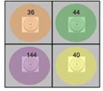
|
|
NOTE:
Any configuration changes made through the profile for cell sizes will overwrite the values set by this operation.
|
When optimizing cells, click Show Advanced to see the following two settings.
|
|
Minimum Power: Select the minimum transmit power that the AP can assign to a particular radio when adjusting automatic cell sizes. The default value is 10 dBm. |
|
n
|
Cell Size Overlap (%): Enter the percentage of cell overlap that will be allowed when the AP is determining automatic cell sizes. For 100% overlap, the power is adjusted such that neighboring APs that hear each other best will hear each other at -70 dBm. For 0% overlap, that number is -90 dBm. The default value is 50%. |
The More button lets you Reboot or Reset APs or mark them as out of service. Reset will return APs to their factory settings (except that their IP settings are preserved), and reboot them. Click Take Out of Service to set these APs as offline administratively, or click Put in Service to restore them to operation. For example, you might want to set an AP offline when physical maintenance is being performed in part of a building, so that the AP won’t trigger alerts. When an AP has been set to offline administratively, it will continue to operate and connect users. but it will not trigger AP down alerts or be counted as offline in dashboard displays. Any existing alerts will be closed when an AP is set offline.
The More button can also be used to Decommission APs—this option is only offered for APs models that are still supported by Cambium Xirrus. Decommissioning an AP removes it from management by XMS, and it will no longer be included on tthe My Network—Access Points tab. Decommissioned APs can then be added to a different domain. See Add APs to XMS-Cloud (The Add/Remove Page). Be patient—it may take a long time for the decommission and add to be reflected in the AP list on this page. Note that models that are no longer supported (i.e., end-of-life) are automatically decommissioned. You will be notified before this occurs, and the APs to be decommissioned will be listed. These APs cannot be restored to the list. Note that when an AP is decommissioned, it will still connect clients and handle network traffic. It simply will not be managed by XMS-Cloud.
Bulk Configuration of Access Point Details
AP details such as Hostname, Location, Groups, and Profiles vary for different APs. For example, Hostname is different for every AP. Editing these details one at a time for a large number of APs is tedious and time-consuming. Using the import feature, you can read in these settings for many APs at once from a spreadsheet.
Before using the import feature, you can download a sample .csv file showing the expected format by clicking Manage Access Points on the upper right of the page.
Select Get template from the drop-down list. Create your .csv file in the same format. You must keep the column header row without modifying it—the columns need to be kept in the same order. APs are identified by their serial numbers. For each AP to be edited, enter its serial number. In the same row, enter the desired values for its Hostname, Location, Profile, and Group. If you enter a Group name that is not already in use, a new Group will be defined with that name. Only one Group may be specified for each AP—you cannot have multiple Group columns.
To import a spreadsheet, click Manage Access Points, then click Import. You will be asked whether you wish to override existing AP settings:
|
|
Yes — Each cell in the imported file will replace the corresponding setting in the specified APs. Only non-blank cells are used—for example, if an AP is currently a member of Group SF2, but the AP’s Group column is blank, the Group setting on that AP is left unchanged. |
|
|
No — The values in the imported file will only replace AP settings whose value has not been previously set. |
Use the Export link if you want a spreadsheet including all APs. All APs are listed, regardless of whether the filter for Profile/Group is in use. A header line labels the columns of the spreadsheet.
There are two types of spreadsheets that can be exported:
|
|
All Access Points — All APs are listed. All possible columns are included, whether or not they have been selected as described in Customizing the Page Display. |
|
|
All Radio Configurations — All AP radios are listed. The radio’s AP is identified by host name, serial number, and IP address. All radio settings are shown, such as Enabled/Disabled, Channel, Band, Tx Power, Rx Threshold, etc. |
Customizing the Page Display
You can change the display of this page in various ways. Click a column header to sort the APs based on that column. Click the Column Select button  to choose the columns to display—this allows you to add information to the display such as the software version currently running on a device. Drag items up or down in the Select Columns dialog to change the order in which columns appear. Use the search field to display only APs that include the search string in any position. The search checks for matches in the Hostname, Serial Number, MAC Address, and Location columns. You must type at least 3 characters to start the search, and the search is not case-sensitive. You can also use the Profile/Group drop-down on the upper right to select one of the Profiles, Access Point Groups, or SSIDs to consider when displaying results—only member APs will be displayed.
To see only APs that belong to a subset of the network, see Filters.
Access Point Groups
You can define groups of APs and then select a group when you want to display data for only its member APs. For example, a retail chain might define a group for each of its stores or for each of its departments. The Groups view summarizes the status of member APs for each group, making it easy to see which groups have APs that are offline and drill down with a click to identify the problem APs.
To define a group, open My Network—Access Points and click  to display the Groups page, then click
  . Enter the desired Group Name, and then select its member APs. The same AP can be a member of more than one group. APs from different profiles may be combined in the same group. A Search field allows you to search for a group based on its name. To change the display of groups to a list, click
  on the upper right of the page. Click
  to change the display to tiles again. Note that the maximum number of groups that you can define is limited to half of the number of APs that XMS is managing.
By default, groups are represented as tiles whose color shows their status: green if all member APs are up, and red if at least one AP is down (Out of Service APs are not considered). Click a group to manage it: View, Edit or Delete. Click View to drill down into the group and see an Access Point list showing just member APs, making it easy to locate APs that are down.
AP groups may be used to filter the data displayed in dashboards and reports. On the My Network—Overview Tab, use the Profile/Group drop-down on the upper right to select either a group or a profile to consider when displaying results. For Reports, open an existing report type, click Edit View, and select a profile or group whose APs are to be included.
My Network-Switches
XMS-Cloud supports the complete cnMatrix enterprise switch line with the addition of the EX1000 series models. You can manage the EX1000 series using profiles and policy-based automation (PBA) to streamline core operations and improve network security.
Switch View
Switch View allows the user to manage Switches by editing them and assigning them to profiles. For each Switch it displays the assigned Host Name, Serial Number Version, and IP Address. If these have been configured. It also shows whether the Switches are currently Online (i.e., whether the Cloud is able to connect to and manage the Switches), and the Expiration Date of its Cloud license.
The Status field shows whether the Switches has been Activated for management by the Cloud or not, or whether there is an error condition on the Switches—click the information button next to the status for more details. The number of Alerts issued for this Switches will be shown—click this number to be taken to My Network—Alerts with a filter set to show just the alerts for this Switches. If the Alerts column isn’t displayed, the Customizing the Page Display describes how to add it.
Click the Column Select button  to choose among many different types of information to display, and drag items up or down in this dialog to change the order in which columns appear.
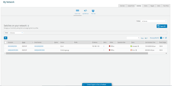
Use the Export link if you want a spreadsheet including all Switches. All Switches are listed, regardless of whether the filter for Profile/Group is in use. A header line labels the columns of the spreadsheet.
Switch Reboot
In Switch view Reboot option is used to remove the current configuration settings. It is recommended when the whole device needs to be reconfigured or to restore to its original default settings.
To reboot the switch:
|
1.
|
Navigate to My Network > Switches > Switch View tab. |
|
2.
|
Select the Switch to be rebooted > click More > and select Reboot from the dropdown. |
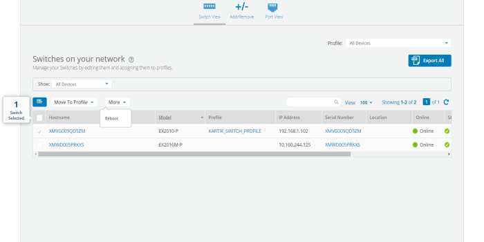
Port Channels
To create a cnMatrix port channel to aggregate ports,
Navigate to the MY NETWORK > Switches page. Select the model of the switch and the ports for that switch that appear. Select the two (or more) ports you want to combine. Then click the Combine Ports button.
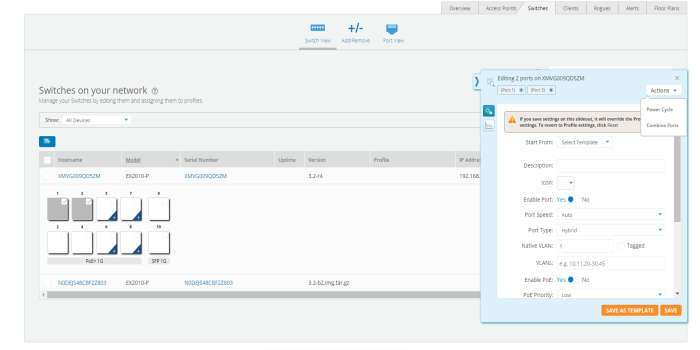
Add Switches to XMS-Cloud (The Add/Remove Page)
To add a cnMatrix switch to XMS-Cloud:
|
1.
|
Navigate to Switches > Add/Remove > +Add Switch to Account. |
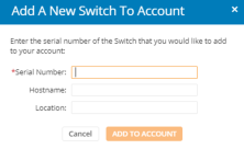
|
2.
|
Enter the new cnMatrix switch Serial Number. |
|
3.
|
Enter the Hostname and Location. |
To manage this switch in a Profile, go to Profiles and either create a new profile or open an existing profile and click the Switches tile. You can either configure the ports individually or apply a pre-configured template. To use PBA policies, click the Policies tile, then under Policy Based Automation, click New Port Automation Policy button. Configure the policy and click Save.
Port View
Port view allows the user to view and manage the individual ports configuration mapped to the individual switches. You can change the display of the client list in various ways. Click the Column Select button to choose among many different types of information to display, and drag items up or down in this dialog to change the order in which columns appear.
Power Cycle provides option to the XMS Admin to reboot or to solve an issue of a device connected with the port.
To power cycle individual switch ports:
|
1.
|
Navigate to My Network > Switches > Port View. |
|
2.
|
Select the port you need to power cycle, click the Actions button > select Power Cycle > click OK. |
My Network—Clients
This page lists clients that have connected to the wireless network. Click a client to see a chart of its Client Health Score Panel and detailed connection information. You also have options for Deleting Clients, or for Blocking Problem Clients from accessing the networkTroubleshooting.
The Show drop-down selects the type of clients to display. All of the choices below except for Online will display another drop-down to select the period of time to consider (seen in the last hour, in the last day, etc., up to all time).
|
|
All Clients — Lists all clients that have connected to the network, whether or not they are currently connected. |
|
|
If user selects All Clients a new column appears to select time period to display. |

|
|
Online — Lists the clients that are currently connected to the network. |
|
|
Offline — Lists all clients that have connected to the network, but are not currently connected. |
|
|
Blocked — Lists all clients who have been blocked from using the network. |
|
|
The Band to display (2.4 GHz and/or 5 GHz/Wired/All) can also be selected. |
You can use the Filter drop-down on the upper right to select one of the Profiles, Access Point Groups, or SSIDs to consider when displaying results — only clients connected to member APs or to the selected SSID will be displayed. You can also use the search field to find a particular client or a set of clients that contain the string you type.
For each entry, the client list shows hostname and IP address, the user name that was used for authentication, the class of device, the last time it connected, the amount of data sent to it, and more. Click the Client Hostname to see Client Health Score Panel for Troubleshooting for this client. You can change the display of the client list in various ways. Click the Column Select button to choose among many different types of information to display, and drag items up or down in this dialog to change the order in which columns appear.
Blocking Problem Clients
XMS-Cloud can de-authorize clients. This is useful in a number of scenarios. For example, you might block the clients of dismissed employees, expelled students, or those who violate wireless usage guidelines. To deny wireless access to selected clients, click the check boxes to the left of these entries and click the Block button above the client list. The Block and Unblock buttons only appear when clients are selected. A blocked client is disconnected from the network, and is not allowed to associate again unless you select the client and use the Unblock button.
Deleting Clients
Deleting a client removes memory of the client from XMS-Cloud—MAC address, hostname, etc., and associated data such as usage statistics, application usage, and connect rate. This is useful for meeting EU General Data Protection Regulation (GDPR) requirements for data protection and privacy for EU citizens—a client can request removal of their data. To delete selected clients, click the checkboxes to the left of these entries and click the Delete button that appears above the client list. Note that the delete feature is only offered for clients that are offline. If a deleted client would have appeared on the Dashboard (for example, in client- related widgets such as Top Clients, or in drill-downs), the entry will be shown as Deleted Client without any details such as Hostname, MAC Address or IP Address.
Client Health Score Panel for Troubleshooting
This slide-out troubleshooting panel shows the current Health Score for the client connection as well as a graph of its value over time. The Health Score is a number from 1 to 10 that summarizes connection quality as measured by the AP radio to which the client is connected. See Health Score Calculation for the factors that are considered in the health score.
Under the score at the top of the panel, current connection information is shown, including signal strength, statistics, and the AP to which the client is connected. The client’s Device Class is also shown. If you prefer to show this client as a different Device Class, click the class and select the desired value from the drop- down list. This change is sent to all APs in this Domain, and this client will display the selected Device Class even if it connects to another AP. Note that the change only affects this particular client, not other devices of exactly the same kind. The change persists unless you change it again. Note that you cannot change the device class of clients connected to X2-120s and XR-320s.
Note that there is a widget you can add to the Dashboard to show Clients (by Lowest Health Scores) to show clients that are experiencing problems.
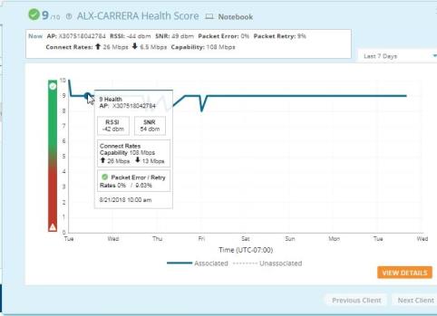
If clients are unable to access the internet or they experience slow download rates, graphs can reveal at a glance the time when things started going wrong. This enables you to go back in time to determine the root cause of a problem, such as authentications, roaming, connection to a new SSID, or infrastructure issues.
On the upper right, select the period of time to display in the graph. Hover the mouse over a point on the graph to show the Health Score and details observed at that time. As above, these include signal strength, statistics, and the AP to which the client is connected. The bottom of this pop-up shows the time at which these values were observed. Note that for periods of time when this client is not connected to the AP, there will be no data.
To drill down for more troubleshooting information, click. This displays individual graphs for RSSI (signal strength), SNR (signal to noise ratio), Error Rates, and Connect Rates. Use the tabs at the upper right to select the desired period of time. Hovering the mouse over a point on the graph displays
data values at that point in time and notes the time when they were observed. In addition, it shows the connection’s SSID. Below these graphs, there is a list of this client’s Top Applications (by Usage). This list is only provided for the top usage clients.
Health Score Calculation
The Health Score gives a quick indication of the connection’s status. The score is a number from 1 (worst) to 10 (best). The number has a green check mark if it is in the acceptable range, and is shown in red if the value is low. This composite score is computed by taking the following factors into account:
|
|
RSSI (Received Signal Strength Indicator) |
|
|
SNR (Signal to Noise Ratio) |
My Network—Rogues
A rogue is a wireless device that is broadcasting an SSID on your network but is not a recognized part of the network, such as a laptop setting up an ad hoc network. Rogues may be benign or malicious—it is up to the network administrator to decide whether action is required. Rogue detection is performed automatically and constantly by the built-in threat-sensing monitor radio in each Access Point if monitoring is enabled (see the Radios button in Managing an Individual AP). XMS collects this information from the Access Points in its managed network. When APs switch off and on, the detected rogues list changes.
This page lists rogues detected by APs on the wireless network managed by XMS. The rogues are listed with the most recently seen first. Thus, if a rogue is no longer detected, it will sink lower in the list over time as newly detected and existing rogues are placed at the head of the list. To see the approximate physical location of a rogue, see My Network—Floor Plans.
The Show drop-down selects the type of rogues to display. The All and Inactive choices will display another drop-down to select the period of time to consider (seen in the last day, week, etc., up to all time).
|
|
All — Lists all detected rogues, whether or not they are currently seen. |
|
|
Active — Lists the rogues that are currently seen by the network. |
|
|
Inactive — Lists detected rogues that are not currently connected. |
You can use the Profile/Group drop-down on the upper right to select one of the Access Point Groups, or Profiles to consider when displaying results—only rogues found by member APs will be displayed. You can also use the search field to find a particular rogue or a set of rogues that contain the string you type.
Valuable information is shown for each rogue, including its MAC Address, the SSID it is broadcasting, its Manufacturer, the Channel it was using and its signal strength (RSSI), the Time Discovered and when Last Seen. The Source Hostname tells which AP discovered this rogue. You can change the display of this page in various ways. Click the Column Select button to choose among different types of information to display, and drag items up or down in the Select Columns dialog to change the order in which columns appear.
My Network—Alerts
XMS-Cloud alerts inform you of problem conditions that have been detected on the wireless network. For example, if a large number of stations are connected to an AP, XMS-Cloud shows an alert for the condition. Change the settings on your account to receive email/text notification when alert conditions occur.
About Alerts
XMS-Cloud issues an alert when it detects conditions such as:
|
|
Access Point lost connectivity (major severity) — This alert is opened when an AP is down (i.e., off line) for more than five minutes, for any reason (powered off, network connection lost, etc.). The alert is closed five minutes after the AP comes back on line. Verify that the AP has power and a network connection. |
|
|
Profile Down (major severity) — All of the APs that belong to a Profile have lost connectivity. This alert is opened when the “last AP” goes down, i.e., an AP is in the offline state for more than 5 minutes and all the other APs in the same Profile are also in the offline state. An Access Point lost connectivity alert is not generated at the same time. The Profile Down alert is closed automatically five minutes after at least one of the profile’s APs comes back on line. |
|
|
Station Count (medium severity) — This alert is opened when the total number of clients connected to an AP passes 30 per radio (i.e., the number of connected stations passes 30 times the number of radios on the AP). This alert simply warns you that an AP is being used heavily, well before the AP has reached its maximum number of connections and stops connecting new clients. You may wish to review wireless performance and consider adding or relocating APs if needed. The alert is closed automatically when the total number of clients connected to an AP falls below an average of 20 per radio. |
|
|
DHCP Failure (medium severity) — This alert is opened when a client reports a self-assigned IP address, indicating DHCP failure. (Often, this is an IP address that starts with 169.254, a common symptom of Windows devices that have been configured for DHCP but are unable to contact a DHCP server.) The alert is closed automatically when no clients on the AP have a self-assigned IP address. |
|
|
Channel Interference (low severity) — This alert is opened when an AP detects another AP or device that might be using one of its configured channels, possibly a rogue AP (see My Network—Rogues). The RSSI of the detected signal must be above -50 dBm for an alert to be triggered. When two nearby APs use the same channel, they can interfere with each other, so this alert makes you aware of potential problems. The alert is closed automatically when the channel interference is no longer detected. The alert can be mitigated by adjusting the transmit power of the offending APs or by changing the channel. |
|
|
Google or Azure Portal (major severity) — This alert is opened when the connection to Google or Azure is lost for more than five minutes. If you have EasyPass Google or EasyPass Microsoft Azure portals, XMS periodically contacts the Google or Azure directory to look for guest accounts that are no longer present. These guest accounts have their EasyPass access revoked. XMS generates an alert of major severity if the system fails to connect to the Google or Azure directory service. The administrator may need to correct the EasyPass portal configuration or re-authenticate with the directory. The alert is cleared when the connection to the directory service is restored. |
Viewing and Managing Alerts
To see Alerts, go to My Network, then do one of the following. (See the image below.)
|
|
Click the Alerts widget in the ribbon at the top of the page (while in the Overview tab). |
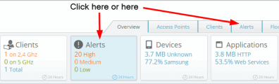
The Alerts list is displayed slightly differently depending on what you clicked to display it.
|
|
The Alerts widget lists the ten latest open alerts. |
|
n
|
The number of alerts of each severity are summarized in the colored boxes as the right. |
|
n
|
The Alerts list shows the most recent alerts first. Alerts that have been closed by XMS-Cloud are not shown. Entries marked with a blue bar at the left have been acknowledged (see the description for the Alerts tab, below). Each entry shows Alert Type, Severity, and the Open Date (the date the condition occurred). Source identifies the cause of the alert, for example, an AP or a profile. If the source is a profile that hasn’t been deleted, its name is a link that you can click to go to the profile (see Profiles). To see AP details, click the Access Point tab, hover over the AP entry and click its Details button . |
|
|
The Alerts tab offers more management options than the Alerts widget. |
|
n
|
The Show options select which alerts to display. You may display only Open or Closed alerts or both, only Acknowledged or Unacknowledged alerts or both, and select a particular Severity level or show all levels. You can use the Profile/Group field to see only the selected APs as described in Filters. |
|
n
|
Alerts may be sorted by clicking on any column header. Click again to sort in the reverse order. To change the columns that are displayed, click the Columns button  . . |
|
n
|
The Alerts list shows the alerts that meet all of the criteria selected in the Show choices above. Each entry shows Alert Type and Severity. Source identifies what generated the alert, for example, an AP or a profile. To see AP details, click the Access Point tab, hover over the AP entry and click its Details button . The State shows whether the alert is still open or has been closed. Alerts are closed by XMS- Cloud automatically when it detects that the problem condition no longer exists—you cannot close an alert manually. The Open Date/ Time (the date the condition occurred) and Close Date/Time (if the alert has been closed) are also shown. |
|
n
|
You may mark alerts as acknowledged for your own convenience. Click the checkboxes to the left of the desired alerts and the Acknowledge button  appears. Click the button to mark the selected entries as acknowledged. Entries that are marked with a blue bar at the left have been acknowledged. To reset acknowledged entries, click their checkboxes and use the Unacknowledge button that appears. Note that the Acknowledge setting is not used in any way by XMS-Cloud, except that it allows you to show only Acknowledged or Unacknowledged alerts if you wish. appears. Click the button to mark the selected entries as acknowledged. Entries that are marked with a blue bar at the left have been acknowledged. To reset acknowledged entries, click their checkboxes and use the Unacknowledge button that appears. Note that the Acknowledge setting is not used in any way by XMS-Cloud, except that it allows you to show only Acknowledged or Unacknowledged alerts if you wish. |
Alert Notifications
If you wish to be notified by email and/or text message when a particular type of alert occurs, set up Notifications for your account as described in My Account.
Syslog Server
Syslog is a resource that can help the network administrator or Cambium Xirrus Customer Support analyze network problems that have caused alerts. APs can forward log messages that describe problem events to a designated syslog server. You can specify the location of a syslog server in each profile, on the General tab.
My Network—Floor Plans
Floor plans offer a detailed view of the locations and status of APs within a building and let you drill down for more information about each AP. A heat map displays the coverage provided by APs. You can drill down from a geographical Map to see the floor plans at a location.
Create Floor Plans
Add floor plans to XMS to represent buildings. Each building may include multiple floors or areas, each with its own floor plan image. Each floor/area image should be a png, jpg, bmp, or gif file. Png files give good results since they scale very well. The maximum file size is 700 kB; smaller images will yield better performance.
|
1.
|
Select My Network on the top toolbar, then select the Floor Plans tab. Click New Building and enter the Building Name. |
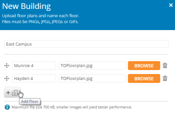
|
2.
|
Enter a floor plan for each floor or area in the building. In the field on the left, enter a name for the floor plan, such as Floor1 or 26-100 Lecture Hall, then browse to the floor plan image. To enter plans for additional floors or areas in the building, click the Add Floor button  . Click OK when you have added all of the areas to be grouped in this building. . Click OK when you have added all of the areas to be grouped in this building. |
Setting Up the Floor Plan
XMS guides you through five numbered steps to set up each floor plan.
|
1.
|
Look for Step  and click Select Environment. This tells XMS about the type of construction in this area—what kind of walls and how closely spaced. Select the best match for the area represented on the floor plan. and click Select Environment. This tells XMS about the type of construction in this area—what kind of walls and how closely spaced. Select the best match for the area represented on the floor plan. |
|
2.
|
For Step  , click the Define Heading button , click the Define Heading button  and drag it in a circle until the needle pointing north is oriented in the correct direction for the floor plan. Some APs have hardware capable of sensing their orientation and are automatically placed on the plan with the correct orientation. This feature requires North to be set correctly and drag it in a circle until the needle pointing north is oriented in the correct direction for the floor plan. Some APs have hardware capable of sensing their orientation and are automatically placed on the plan with the correct orientation. This feature requires North to be set correctly  . . |
|
3.
|
Step  sets the scale of this floor plan so that location information and the RF heat map are computed as accurately as possible. Before you start this step, measure the physical length of a wall or other feature that is represented on the floor plan. Then click the Set Scale symbol sets the scale of this floor plan so that location information and the RF heat map are computed as accurately as possible. Before you start this step, measure the physical length of a wall or other feature that is represented on the floor plan. Then click the Set Scale symbol  . The mouse pointer changes to a cross-hair tool— move it on the plan to one end of the wall or feature that you measured, then click and drag it to the other end of the feature. A line will be drawn between the endpoints. Go back to the Set Scale dialog and enter the physical length that you measured. Click OK. Note that the scale for the plan is now displayed. . The mouse pointer changes to a cross-hair tool— move it on the plan to one end of the wall or feature that you measured, then click and drag it to the other end of the feature. A line will be drawn between the endpoints. Go back to the Set Scale dialog and enter the physical length that you measured. Click OK. Note that the scale for the plan is now displayed. |
Adding APs to the Plan and Orienting Them
Use the steps below to add APs to the floor plan in the locations where they are deployed and to orient them—rotate each AP on the plan to match the actual orientation of its radio 1. This is important for accurately calculating and displaying locations of stations, and for correctly displaying heat contours on the plan. In addition, when you set AP locations accurately, XMS sends each AP its positioning information. This allows APs to send better location information to the Xirrus Position Server and improves integration with analytics servers (see Location Services).
|
4.
|
Step  adds APs to the plan. Click > on the upper right to display the right hand panel, then click the Access Points button as shown in red. adds APs to the plan. Click > on the upper right to display the right hand panel, then click the Access Points button as shown in red. |
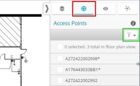
|
a.
|
All of your APs are listed. An asterisk indicates APs that have already been placed on any floor plan. Use the filter button shown in green above to filter the AP list by Model, Profile, IP Address, or Location. A search string may have a wild card (asterisk) at the end to match any item that begins with the string you entered. For example, BUILDING1* will match Building1, Building146, etc. Drop-down lists let you select strings to match—for example, the Model list shows all of the model numbers in your network. |
|
b.
|
Click APs to select or deselect them as shown by their checkboxes. The checkbox at the top of the column will select or deselect all APs. Drag from anywhere in the Access Points list to move the selected APs to wherever you drop them on the map. If they are already on this floor plan, they will be moved to the drop location. If they are currently on another plan, they will be moved to this plan. |
|
c.
|
Click and drag APs on the plan to adjust their locations as needed. |
|
d.
|
Click an AP on the plan to set its orientation. The APs hostname and model are shown. Set Face Position to match the APs mounting position—the LED side is the face. This is set to Down by default, as Cambium Xirrus APs are typically mounted face down. |
|
e.
|
If the AP is not outlined by a blue box as shown below, click the AP again to display it along with additional details. The AP is surrounded by four blue dots. A fifth dot indicates the orientation of radio 1, and it is used as a handle to rotate the AP. Turn the AP until this handle points in the same direction that the physical APs radio 1 does. Moving the mouse out further away from the AP while rotating it slows the rotation and gives you finer control over the orientation. |
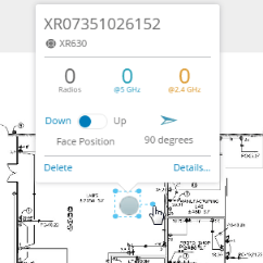
|
f.
|
Use the Details link to configure individualized settings on this AP that are not handled by the profile. For example, you might want to enter a Location (for example, Room 410), and set one of the radios to the 2.4 GHz band. See Managing an Individual AP for a description of setting Details. |
|
g.
|
Repeat this process until all APs are located, oriented, and configured. |
|
5.
|
For Step  , click Place on Map to place this building on the main map. Use the search feature to enter the name or zip code of the town where the building is located. Zoom in until you find the exact location (switching from the map view to the satellite view may be helpful), then click the Set floor plan location button , click Place on Map to place this building on the main map. Use the search feature to enter the name or zip code of the town where the building is located. Zoom in until you find the exact location (switching from the map view to the satellite view may be helpful), then click the Set floor plan location button  . Drag and drop the cursor to the desired position. . Drag and drop the cursor to the desired position. |
|
6.
|
Repeat these steps for all floor plans that are part of this building. |
Managing Floor Plans
A pull-out panel at the right of the window manages the selected building’s floor plans.
|
1.
|
If you haven’t already selected a building, select one from the main My Network—Floor Plans tab. Then click > on the upper right to open the right hand panel. Select the Floor Plans button, as shown below in red. All of the floor plans defined for this building are shown. Hover the mouse over a floor plan to see its name. |
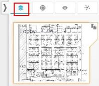
|
3.
|
Offline APs are shown in red and online APs are shown in green. Click an AP to see its model, hostname, number of radios, how many radios are active in the 5 GHz and 2.4 GHz bands, and positioning information. Click the Details link at the lower right to display a panel with detailed AP information and configuration options. This panel provides the same information and as Managing Individual an AP, which is part of the My Network—Access Points tab. |
|
4.
|
In the right hand panel, the Settings tab  includes an Opacity option that allows you to fade the floor plan. Lower values make the floor plan less visible. Other settings options apply to, Heat Map, Station and Rouge. See those sections for details. includes an Opacity option that allows you to fade the floor plan. Lower values make the floor plan less visible. Other settings options apply to, Heat Map, Station and Rouge. See those sections for details. |
|
5.
|
You can superimpose a Heat Map on the floor plan to show signal strength coverage of the area. See Heat Map for details. |
|
6.
|
You can view stations on the floor plan. See Stations details. |
|
7.
|
Advanced users can click  on the upper right of the right hand panel to display channel usage for APs on the floorplan. See Channels and Planning for details. on the upper right of the right hand panel to display channel usage for APs on the floorplan. See Channels and Planning for details. |
|
8.
|
Click Go to dashboard map on the bottom left of the window to return to the dashboard Map. |
|
9.
|
To adjust the location of this floor plan on the geographic map, click Place on map on the bottom left of the window. This returns to the dashboard Map. Click the desired “pin” on the map, then click the Redraw link and drag the pin to the desired location. Click Return to Floor Plan on the bottom left when you are done. |
Heat Map
Click the Heat Map button  on the left side of the window to superimpose a heat map on the floor plan. A heat map shows wireless coverage at your site based on measurements observed by APs. It visualizes the RF environment provided by your wireless network. Areas of low coverage are immediately visible. The map incorporates directional antenna coverage on a per radio basis, and readings are enhanced by means of inter-AP correction. By leveraging the RF analysis capabilities available on the AP, XMS-Cloud makes it easy to view the changing RF environment.
The color ribbon on the bottom of the map is a legend that shows signal strength. Click a color to see the RSSI value that it represents. Blue areas have low signal strength, while areas ranging from green to red have good to excellent signal strength.

In the right hand panel, the Settings tab includes Heat Map options:
|
|
Select the Bands that are displayed (2.4 GHz, 5 GHz, or both). |
|
|
Select the minimum RSSI Level to show. |
|
|
Select how intensely to show the heat map colors by moving the slider underneath Show Heat Map. Lower values fade the heap map. |
Stations
Click the Stations button  on the left side of the window to show the approximate locations of stations on the floor plan. Note that Location Reporting must be enabled to allow station locations to be determined. On the right hand panel, the Settings tab
  includes an option to enable Location Reporting. This enables location reporting for all floor plans in this building. It may take up to five minutes for locations to be shown. This feature is not controlled by the Location Services setting in profiles.
Different types of stations are represented with different graphics (if the type is known). Hover over a station to see detailed information such as device type, host name, and MAC address. Only associated stations are included, i.e., stations that have been detected but have not connected to an AP are not shown.
Channels and Planning
This visual tool is for advanced users who want to set channel assignments manually. It shows channel usage by APs so that you can see when adjacent APs use the same channel, which may hinder performance. Use it to help make sure that neighboring APs’ channels don't overlap.
Click > on the upper right to open the right hand panel, then click the Channels button  . This displays channel usage for APs on the floor plan. All channels are listed, and channels that are used by at least two APs show the count of APs using this channel. For example,
  indicates that channel 36 is used by three APs. Select a channel’s checkbox to show which APs use that channel. Note that the circles are a fixed-size general representation, and are not meant to accurately show coverage area. Signal strength and radio directionality are not taken into account.
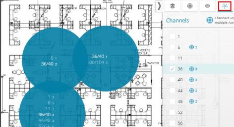
Each circle shows the channels assigned to radios on the AP, sorted by channel. For example, in the AP below, Radio 1 uses bonded channels 36/40 and Radio 2 uses 100/104. The channels that you selected are highlighted in white.

Rogues
You can display rogue wireless devices on the floor plan. Click the Rogues symbol  on the left side of the floor plan to show the approximate physical locations where rogues were detected. Note that Location Reporting must be enabled to allow rogue locations to be determined. On the right hand panel, the Settings tab includes an option to enable Location Reporting. This setting applies to all floor plans in this building. It may take up to five minutes for locations to be shown. This feature is not controlled by the Location Services setting in profiles.
Rogues are indicated on the map with red rogue symbols  . Multiple rogues that are physically very close to each other are shown just slightly offset from each other. To see the individual rogues in this case, zoom the map in until the rogues are shown separated. Click on a rogue to see its identifying information including MAC Address, Manufacturer, SSID, Channel, and the Source Hostname (i.e., the AP that detected this rogue). Click the Details link to see this rogue on the My Network—Rogues tab.
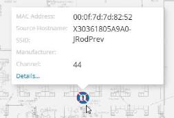
Note that a rogue might be located outside the borders of the floor plan. In this case, zoom out to show areas outside the borders and see if there are any rogues beyond the area of the floor plan.
Reports
XMS-Cloud offers reports about usage and performance for wireless Access Points and clients within the network, featuring information such as usage by 2.4 GHz or 5 GHz, usage by client type or application type, availability (uptime), or wireless data (throughput). A number of predefined report types are provided for you to run, and you may also design your own report types, including customizing their appearance and their content. You can filter a report to include only results for the APs in a particular profile or group. Analytics provide information about customers numbers and dwell time.
Viewing, Using, and Modifying Reports
To use reports, click Reports on the menu bar. Select one of the “favorite” report types listed on the drop-down, or select View All Reports as shown below to list all report types. Simply click one of the existing report types to run it and view the results. If you wish to create your own custom report type, see Creating a Report Type.
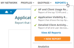
Reports have a title page and one or more data pages. Each data page summarizes an aspect of network usage or performance by presenting a set of data from a widget (the same widgets are presented on the dashboard) over a set period of time. For example, it might show Data Throughput for APs or Top Applications by Usage. A data page typically shows one or two charts at the top, such as a pie chart and a bar chart with different representations of the same data. More detailed information is shown in a table below the charts. The charts indicate the period of time presented on the page. The data in the report is refreshed each time you click to open it and represents the state of the network at that time.
A report is essentially an instantaneous view of data for the selected period. You cannot save report output, although you can print a report or save it as a PDF.
Viewing a Report
Select a report to view it. The following options are available while viewing. See Working with Reports below for other options, like editing or duplicating a report.
|
|
Print — While viewing a report, click the Print button  . A preview of the printout is displayed. Click Print again to open a dialog for printing. . A preview of the printout is displayed. Click Print again to open a dialog for printing. |
|
|
PDF — To create a PDF instead of printing, display the print dialog as described above. Change the Destination by clicking the Change button  Select Save as PDF. Then click the Print button to proceed. Your browser must support Save as PDF to use this feature. Select Save as PDF. Then click the Print button to proceed. Your browser must support Save as PDF to use this feature. |
|
|
Edit View — While viewing a report, the  Edit View button appears on the upper right, next to the print button. Click it to customize your report in one of these ways: Edit View button appears on the upper right, next to the print button. Click it to customize your report in one of these ways: |
|
n
|
Select one of your Profiles, Access Point Groups, or SSIDs from the drop-down list. This filters the report to show only data from the selected portion of the network (note that in order to filter by SSID, you must set Default Firmware to Technology in Firmware Upgrades.) To revert to seeing data for all APs, select All Access Points. |
|
n
|
Set Override Date/Time to Yes to change the End Time of the report. You may also choose to change the Start Time. |
Working with Reports
You may edit, duplicate, or delete reports, or add or remove favorite status. These options are offered on the report display, or from the View All Reports list.
|
|
On the report display click the settings button  , as shown below, to display a drop-down list of options. , as shown below, to display a drop-down list of options. |
|
|
On the View All Reports list, hover the mouse anywhere over the desired report to show buttons for the options that are available. |
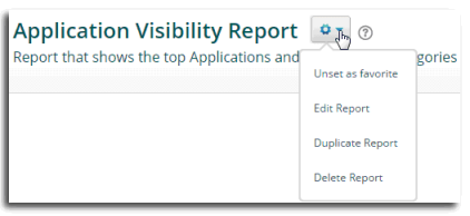
The following options are available:
|
|
Edit Report — You may edit the report type to add or delete pages, change the widgets displayed, select a different time period, or change any of the other settings (including the title) that are described in Creating a Report Type. Note that predefined reports may be edited. You will not see the Edit View button while you are in edit mode—it reappears after you save your changes. |
|
|
Duplicate Report — Use this to make a new report that is similar to an existing report. Then you may edit the report to change its title and other settings as described above. |
|
|
Delete Report — XMS-Cloud will ask you to verify the deletion. |
|
|
Favorite — You may set or clear favorite status. Favorite reports will be listed on the drop-down list that is shown when you click Reports on the main menu bar. Anytime you view a list of reports, the favorite reports are flagged with a green check mark . |
Creating a Report Type
Use the Report Template to easily create and customize the report types you need. To create a new report type, click Reports on the menu bar, then click  . The Report Template appears and guides you through report creation. Set up the following pages:
At any point in the creation process, you may click the Save button  on the upper right to save this report type, or click Cancel to abandon your changes and exit report editing mode. If you have made edits, you may click Undo All to reverse your edits and return to the last saved version of this report.
Configure Title Page
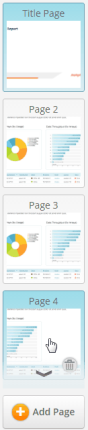
When you create a report type, the Report Template displays the Configure Title Page form. Use this page to configure the cover of the report. You will set up the data content of the report later in Configure Page 2, etc.
Enter a unique Report Name. You may also enter an optional Description of the purpose of this report. This will be shown under the title in various lists and displays, but won’t appear in printouts.
To customize the report with your Logo, click Browse. You may select one of the displayed previously uploaded images, or click Upload new image to browse to an image, or click Add external image to specify the image using its URL. The logo will be displayed on the sample title page display. The display of the logo is fixed—it cannot be resized or moved on the page. If you don’t wish to use the logo, click Remove Logo above the Browse button.
You may set this report as a favorite, to make it appear in the Reports menu drop-down list. Click the Settings button next to your report name and select Set as favorite. Anytime you view a list of reports, the favorite reports are flagged with a green check mark  . To clear favorite status on a report, select the report and use the Settings button.
You may save the report periodically as you work on it, and return to edit it and add further settings later. See Working with Reports.
Configure Page 2, etc.
To add a data page to the report, click  on the bottom right of the sample page display. The Configure Page 2 Template appears.
Specify the type of data included in your report by selecting from a list of “widgets”. These are very similar to the widgets that are available to add to My Network > Overview (the dashboard). Select a Widget from the drop-down list. Add a Description for this page if desired. Select the Time Range. As you make modifications, their effect is shown directly on the prototype page.
To add more data pages to the report, click again. Select the widget to appear on the newly added page, as before. To go back to editing a previous page, use the page selection scroll ribbon on the right of the window, as shown. Note that as you hover over a page in the scroll ribbon, an arrow at the top or bottom appears if needed to allow you to scroll.
Click the Save button when you are done. Your new report type will be listed along with the other reports. You may view the report and make edits to it as shown in Viewing, Using, and Modifying Reports.
After saving, the Edit View button appears on the upper right, next to the print button. Click it to customize your report in one of these ways:
|
|
Select a profile from the drop-down list. This filters the report to show only data from APs in the selected profile. |
|
|
Set Override Date/Time to Yes to change the End Time of the report. You may also choose to change the Start Time. |
Schedule Email Reports
Use this feature to send the current report as a one-time email or to schedule recurring reports. Select a report, and click  on the upper right. Enter the email addresses of recipients as a comma-separated list. By default, this generates a one-time email of the report that you are viewing using its current settings. The email will show your email address as the person who requested that the report be sent.
To automatically run the report and email a copy on a regular basis, set Make Recurring to Yes. Select how often to send the report, when to send it, and what time zone to use for determining when to send it. Note that if you use the Edit View button to Override Date/Time, then you cannot use Email Report to set up a recurring report.
To review the list of scheduled reports, click Reports on the menu bar, then select View All Reports. Click the Scheduled tab, as shown below.
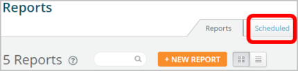
Hover the mouse over an entry to edit or delete it, or you may click an entry’s checkbox and use the Delete button that appears above the list.
Analytics
XMS provides client analytics charting information such as the number of unique visitors to your network and how long they stay connected. You can customize different visualizations (analytics charts) just as you can set up different reports. Create a visualization by clicking Reports and selecting Analytics. Click the plus sign  and enter a Visualization Name. Select the Visualization Type:
|
|
Number of Visitors is the number of associations to the wireless network for the selected time period as a total, and also separated into the number of new clients and recurring clients (determined by the device MAC address). For example, this could tell you how many daily visitors a store has connecting to wireless, and how many are returning visitors. |
|
|
Average Dwell Time groups visitors by how long they stay connected. |
Select one of the Access Point Groups to display data for a particular set of APs, such as those at one location, otherwise data for All Access Points is displayed by default. Finally, select the desired Date Range to include in the output (dates that are not permissible are grayed out). Click Add to display the resulting chart.
Click the plus sign at any time to add a new visualization or to select an existing one to add to the display. All previously created visualizations are listed on the Previous tab. Select one and click Add to include it in the displayed charts. Previous visualization rows may be deleted.
To edit or delete a displayed chart, click the menu button  on the upper right of the chart. You can send the report in an email by clicking .
Command Center
|
|
NOTE:
Command Center is only present if you have an XMS - Cloud account that allows you to manage multiple separate networks. See Step 1 under Domains, below to check whether you have Command Center. If you do not see the Command Center link, then you do not have this type of account.
|
Use Command Center to define a separate network (called a domain), and add Cambium Xirrus devices to it, for each of multiple customers, branches, schools, or locations. Command Center simply offers a way for you to define and manage separate networks without asking Cambium Xirrus to give you separate accounts. You can create user accounts and restrict them to managing only particular domains.
A domain treats the APs that you assign to it as a separate wireless network, independent of the devices in any other domains you have created. Each domain has its own profiles, map page, alerts, etc. When you select a domain to work with, only the information relevant to that domain is displayed or modified by XMS-Cloud.
Follow the steps below to manage separate domains in the XMS-Cloud Command Center.
|
1.
|
Access Command Center — Click Command Center at the top of the window. The Dashboard (for Command Center) is displayed, showing currently defined domains. Note that if you are not currently in the top level domain, the My Network link appears instead of Command Center. In that case, click the user button  at the upper right of the cloud window and select the Command Center option from the drop-down list. at the upper right of the cloud window and select the Command Center option from the drop-down list. |
|
2.
|
Each network to be managed separately is called a domain. Your first step is to create a domain for each of these networks, as described in Domains. |
Dashboard (for Command Center)
The dashboard summarizes the status of all domains, providing a quick indication of any domains that have problem APs requiring attention. The dashboard is available from the parent (top level) domain only. Domains that have offline Cambium Xirrus devices are shown in red. Domains with the highest severity of problems (i.e., the highest percentage of devices offline) are shown first. If all of a domain’s APs are online, it is shown in green. Use the Search for Domains feature to reduce the number of domains shown. Only domains that contain the search string will be shown.
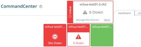
If all APs in a domain are down, it is flagged with Site Down, otherwise the number that are down is shown. Click a domain to expand it. Click More to go to the Domains tab to view/edit the settings for this domain. Click Manage this Domain to select this domain for network management, and switch to its home window (the My Network— Overview Tab). See Managing a Domain Network.
Domains
Create a domain for each network that is to be managed separately. Your overall XMS-Cloud account with Cambium Xirrus is considered to be the parent (top level) domain. The parent domain is predefined, and has the same name as your XMS- Cloud customer account. All of the domains that you create are listed under the parent domain. You cannot nest domains under any other domain than the single parent domain.
The parent domain holds all of your APs that have not yet been assigned to other domains. Don’t use the parent domain for other purposes. For example, no statistics are collected for the parent, so its My Network page will not show any data. Similarly, it is not useful to create items like EasyPass portals for the parent domain.
Use the following steps to define the domains for your networks.
|
1.
|
Access Command Center — Click Command Center at the top of the window. Note that if you are not currently in the top level domain, the My Network link appears instead of Command Center. In that case, click the user button at the upper right of the cloud window and select the Command Center option from the drop-down list. The Dashboard (for Command Center) is displayed, showing currently defined domains. |
|
3.
|
To make changes to a previously defined domain, hover anywhere over the domain entry to display the available options  . Hover over a button to see a tool-tip showing its function: . Hover over a button to see a tool-tip showing its function: |
|
|
Edit Domain  displays the Domain details window. You may edit the name or description of the domain. Click the Users button displays the Domain details window. You may edit the name or description of the domain. Click the Users button  in the left margin to manage users —for details, see Users (for Command Center).Click the Access Points button in the left margin to manage users —for details, see Users (for Command Center).Click the Access Points button in the left margin to view the devices that are assigned to this domain—for details, see Access Points (for Domains). in the left margin to view the devices that are assigned to this domain—for details, see Access Points (for Domains). |
|
|
Manage this Domain  selects this domain for network management, and switches to the home window (the My Network Overview Tab). At this point, all information displayed on this page and for Profiles, EasyPass, Reports, and User Accounts will show data and modify settings only for Cambium Xirrus devices in this domain. See Managing a Domain Network. selects this domain for network management, and switches to the home window (the My Network Overview Tab). At this point, all information displayed on this page and for Profiles, EasyPass, Reports, and User Accounts will show data and modify settings only for Cambium Xirrus devices in this domain. See Managing a Domain Network. |
|
|
The Delete button removes this domain and all items related to it. For example, profiles for this domain are deleted. All of the domain’s devices must be unassigned before the domain can be deleted. |
Users (for Command Center)
The Users tab manages XMS-Cloud users who have privileges to manage or view one or more specific domains. This tab lists all currently defined users.
Users have one of four roles (i.e., privilege levels):
|
|
Command Center Admin — This “super-administrator” has complete access to Command Center features. A Command Center Admin can create domains and users, assign devices to domains, and manage any domain. Additional Command Center Admins may be created. The other three user roles below do not have these privileges, and cannot access Command Center (it will not be visible for non-CommandCenter Admin users.) When you become an XMS-Cloud customer with a Command Center account, the account login shown in your Welcome email from Cambium Xirrus has Command Center Admin privileges and provides access to the Command Center. The Command Center Admin role is only available when you are in the parent domain (when you open the Command Center, XMS-Cloud automatically switches to the parent domain). |
The other three user roles have access to the domains that you specify, but they cannot access the Command Center. A user account created for a domain here is exactly the same as one created under Settings > User Accounts when you are managing that domain as described in Managing a Domain Network. Creating users in the Command Center simply offers the convenience of creating the same account for multiple domains in one step, rather than having to switch to each domain and create an account there, one domain at a time.
Two different names for each role are offered:Domain and XMS roles. The privileges allowed are identical. Use them as a convenience to distinguish between accounts of users that belong to the parent organization (Domain roles), and accounts of users that belong to other organizations (XMS roles). For example, say that a corporate office park named ABC-Park is the primary XMS- Cloud subscriber. The accounts that it sets up for its own employees have Domain roles (Domain Admin, Domain User, or Domain Read-only). ABC-Park sets up an individual domain for each of its tenant companies. The accounts that it sets up for employees of its tenant companies all have XMS roles (XMS Admin, XMS User, or XMS Read-only). This allows ABC-Park personnel to distinguish at a glance between its users and those that belong to its tenants.
|
|
XMS User or Domain User privileges are similar to admin privileges, except that they cannot use Provider Management or create any of the User Accounts described in Settings (these two tabs are not shown to those with User privileges). |
|
|
XMS Read Only or Domain Read Only privileges allow the user to view information and use features such as Reports, but not save any changes. Some links and buttons that would allow users to make changes are not shown—for example, Save and New Profile buttons are not shown. Create users for domains as described below. |
|
1.
|
At the upper right of the cloud portal window, click the user button  and select Command Center from the drop-down list. Select the Users tab. and select Command Center from the drop-down list. Select the Users tab. |
|
2.
|
Click the New User button  . Enter the FirstName and LastName. Enter the user’s Email address—this must be a valid address, and it will be used as the account’s user name for logging in as well as for sending email notifications for user accounts. . Enter the FirstName and LastName. Enter the user’s Email address—this must be a valid address, and it will be used as the account’s user name for logging in as well as for sending email notifications for user accounts. |
|
3.
|
Click the Domains button  in the left margin of the User Details window to add the domains that this user can access, along with a role for each domain. Click in the left margin of the User Details window to add the domains that this user can access, along with a role for each domain. Click  . From the Domain drop-down list, select a domain that this user is allowed to access. Note that if you give the user access to the parent domain, access is also granted to all the under lying domains. . From the Domain drop-down list, select a domain that this user is allowed to access. Note that if you give the user access to the parent domain, access is also granted to all the under lying domains. |
|
4.
|
Select the user type from the Roledrop-down list. The four role types aredescribed above at the beginning of this section. Note that if you set the Domain to the parent domain, you have the option to set the Role to Command Center Admin. This user will have access to the Command Center and to all domains. Other domains do not offer the Command Center Admin role. |
|
5.
|
Click Apply,and the new Domain and Role will be listed.You may continue to add as many domains as you wish. The user may have a number of domains, with a separate role for each. Click Save when done. |
|
6.
|
From the Users list, you may modify a user’s domains and roles. Hover over an entry in the list, and you may click a button to edit or delete the entry. |
|
7.
|
The user will be notified of the new account at the email address that was entered. The message will include a link for accessing the cloud as well as a temporary password. |
Access Points (for Domains)
This tab lists all of your APs, and shows the assigned domain, or whether they have not yet been assigned to a domain. See Add APs to XMS-Cloud (The Add/Remove page) to assign APs to domains.
|
|
NOTE:
You cannot remove an AP from a domain unless Cambium Xirruss shows you as the registered owner of the AP .For example, if you are a managed service provider using Command Center and your customer owns an AP directly, you will not be able to unassign the AP from a domain and move it to a different one.
|
|
1.
|
Click the user button at the upper right of the cloud window, and select Command Center from the drop-down list. Select the Access Points tab. Note that the Expiration Date column displays the date that each device’s XMS-Cloud license expires. Expired devices cannot use features such as Profiles and Easy Pass, but will otherwise continue to serve clients. Note that you can click any column header to sort based on that column and click again to sort in the reverse order. Use the search function to narrow down the display to devices with matching model types or serial numbers. |
|
2.
|
Hover over an entry to display the View/Edit button . Click it to manage the devices. (To manage multiple devices at one time, see Step 4.) |
|
3.
|
The Next and Previous buttons at the bottom of the edit window can be used as a convenient way to scroll through the devices and change their assignments. |
|
4.
|
To manage multiple APs at one time, select the desired entries using the checkboxes in the first column. For APs, to take the selected entries out of service (i.e., mark them as offline administratively) or put them back in service, click the More button. For example, you might want to set an AP as offline when physical maintenance is being performed in part of a building so that you won’t receive alerts from the AP. When an AP has been set to offline administratively, it will not trigger AP down alerts or be counted as offline in dashboard displays. Any existing alerts will be closed when an AP is set offline. When an AP is taken out of service, it will continue to operate and connect users. |
|
5.
|
To export a list of devices as a .csv (comma-separated values) file suitable for use with Excel and other applications, click the Export All button  on the upper right. All of the entries displayed on the screen are included in the file. on the upper right. All of the entries displayed on the screen are included in the file. |
Managing a Domain Network
When a domain user logs in to XMS-Cloud, the menu bar at the top left of the window shows the domain that is currently being managed. Click the selection button  next to the domain name to see a drop-down with the domains that this user can access. If a large number of domains are involved, you can enter a search string to narrow down the list to show only domains with names that contain the search string in any position.
When you select a domain, the My Network page for that domain is displayed. XMS-Cloud works with and displays only that network. XMS-Cloud acts as if the current domain is the only one it knows about. For example, you may create Profiles and EasyPass portals in different domains with the same name, and they may have entirely different settings (please take into consideration whether this will be confusing for users to work with, if they are managing multiple domains).
Users may switch to another domain for which they have access privileges at any time. The Cloud will ask whether to save any changes before switching to the new domain. Note that if you go to the Command Center, your domain is switched automatically to the parent (top-level) domain.
Users may manage Settings for the current domain according to their privileges. For example, any user role except for Read Only may add new User Accounts for this domain. When these users log in to XMS-Cloud, they will be in this domain, and they will not see the drop-down (shown above) that offers other domains.
Deploying Copies of a Profile to Multiple Domains
In many cases, it may be useful to have similar Profiles in multiple domains. Start by creating a profile in the parent domain. Modify settings as desired. When done, copy it to the desired domains.
|
|
For a profile, click the Settings button next to the profile name and select Deploy to Domain from the drop-down list, as shown below. |
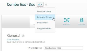
Note that the Deploy to Domain menu option is only available in the parent domain. You will not see it in lower domains. Change the Name for the copy if you wish, or leave it the same. Select the Domain that will receive this copy. You can only select one domain at a time. To copy to multiple domains, repeat this process for as many domains as desired. If this is to be the default profile in the target domain, select Yes for Set as default. Click Deploy when done.
When a profile is deployed to a domain, all settings are the same as for the original (including its status as read-only or editable), with the following exceptions:
|
|
If you copy a default profile, the copy will not be the default unless you set this option as described above. You may also set it as the default when you are modifying the copy. |
|
|
If there is a Captive Portal (EasyPass or other type) assigned to an SSID in this profile, it will not be copied (the SSID’s Access Control is set to None, and its encryption is set to Open/None). Similarly, an SSID’s Airwatch setting is not copied. In addition, the Airwatch settings in Add-on Solutions are not copied. |
To modify a profile that you have deployed, switch to its domain. Any user of that domain who has privileges to modify profiles can make changes to the copy. Profile copies in different domains can be tweaked with separate customizations in each domain.
Troubleshooting
Troubleshooting offers the following pages:
|
|
Audit Trail—Shows a log of changes made to your network. |
|
|
Messages — shows a log of system and account notices. |
To access Troubleshooting, click the user button at the upper right of the cloud window, and select Troubleshooting from the drop-down list.
Audit Trail
This list shows a record of changes that you have made to your network and your account settings using XMS-Cloud via the user interface, including configuration changes to a particular AP, changes to Profiles, EasyPass, Settings, or My Network—Alerts(acknowledge/unacknowledge). (Changes made to a particular AP via CLI are shown in Command Line History.) This does not include such things as changes to the way your user interface is displayed (e.g., customizing your dashboard).
Each audit entry includes the email address of the User that made the change, the Time that it was made, the type of Action (Create, Update, or Delete), and Detail (a description of the action and the item that was changed).
Audit entries may be sorted by clicking on any column header. Click again to sort in the reverse order. You may adjust the View setting to change the number of entries shown per page. To display only entries whose Detail column contains a particular string in any position, enter the string in the Search Audit Detail field above the Audit list. The Audit Trail entries may be saved as a comma-separated values file (csv) suitable for use with Excel and other applications by clicking the Export All button  on the upper right.
Command Line History
This list shows a record of changes that you have made to your APs using CLI via XMS-Cloud. (To access CLI for an AP, go to My Network > Access Points, hover over an AP, click the Details button , and then click the CLI button  .)
.)
Each audit entry includes the email address of the User that made the change, the Time that it was made, the Access Point that was changed, and the Command that was executed).
Command Line History entries may be sorted by clicking on any column header. Click again to sort in the reverse order. You may adjust the View setting to change the number of entries shown per page. To display only entries whose Command column contains a particular string in any position, enter the string in the Search Commands field above the Audit list.
The Command Line History entries may be saved as a comma-separated values file (csv) by clicking Export All on the upper right.
Messages
This list is a record of messages and general announcements that have been presented to you by XMS-Cloud. It includes broadcast messages such as past System Maintenance Announcements, and notices specific to your account such as Subscription Expiration warnings.
Settings
This section describes the use of Settings options, available from the drop-down list that displays when you click your name next to the user button at the upper right of the cloud window, as shown below.
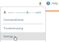
These settings include the following pages:
|
|
My Account—Sets up contact information that allows you to be notified of problems that occur. You may change your password as well. |
|
|
Command Center—Redirect customer support requests to your own support organization. |
|
|
User Accounts—Allows you to add accounts for additional XMS users. |
|
|
Add-on Solutions—Set up use of services from Cambium Xirrus technology partners, such as AirWatch Mobile Device Management. |
|
|
Firmware Upgrades—Specify when upgrades may be performed and what type of software upgrades you want to install. |
|
|
System—Specify how long client data is to be retained in XMS-Cloud. |
To Manage Settings
|
|
Click the user button at the upper right of the cloud window and select the Settings option from the drop-down list. |
|
|
Proceed to the desired tab. |
My Account
Use this page to change your password or to set up contact information for your account. This contact information is used for notification of conditions such as Access Point Down My Network—Alerts.
|
1.
|
Click the user button at the upper right of the cloud window and select the Settings option from the drop-down list. Select the My Account tab. |
|
2.
|
For Contact Information, enter your First and Last name. The Additional Details field may be used to enter information for reference purposes, if desired. |
|
3.
|
Enter your Primary Email address. This is used as your user name for logging into the cloud, and email notifications use this address. |
|
4.
|
For Mobile, first click the field just after the label Mobile Number, select the country of your mobile carrier from the drop-down list, and enter your mobile number (dashes or periods are optional). Select your Mobile Carrier from the drop-down list. The choices shown depend on the country that you selected and the providers that are enabled on the Provider Management tab. Please see Provider Management if a desired carrier is not shown or if too many carriers are shown. |
|
5.
|
In the Alert Notifications section, specify whether or not to use the default settings for notification of network problems. If you select No, then for each type of alert notification (such as Access Point Down), click the checkboxes to select whether to notify via Email and/or SMS or not at all. The notification will contain a description of the problem condition, for example, that an AP has gone off-line. If you enable SMS, a text message will be sent to your mobile number. For more information about the alert types that can trigger notifications, see About Alerts. |
|
|
NOTE:
If you have an XMS-Cloud account with Command Center, you can change your account’s default Alert Notifications settings. Set Yes for Do you want to use the default notification settings for this account? Then you may use the check boxes to change the default values. These default values will apply to your account for all of the domains that you are allowed to access.
|
|
6.
|
Use the System Notifications section if you want to stop receiving XMS- Cloud system email messages for conditions such as system maintenance or license expirations. To stop receiving a type of notification email, clear its checkbox. |
|
7.
|
Use the Change Password button if you wish to change the password for this account. Note that a password expires after 90 days, and you will be required to change it the next time that you log in after expiration. |
|
8.
|
Select your Timezone from the drop-down list. Times displayed in such places as Clients on your network and Alerts will use your time zone. |
|
9.
|
Each change to the account is saved as you finish it, and the message “Account Settings Saved” will be displayed briefly as you proceed to the next field. |
Command Center
User requests from the Contact Support link at the bottom right of the XMS- Cloud page are normally sent to Cambium Xirrus customer support. The Command Center setting lets you redirect support requests to your own support organization. For example, Managed Service Providers (MSPs) can use this to have customers contact them directly for support. It is only available for XMS- Cloud accounts with Command Center, and it is only displayed for the Command Center Admin—the administrator of the top-level domain.
|
|
Set Contact Support Email to the desired email address for support requests, such as the address of your support ticketing system. Requests will be sent to this address instead of Cambium Xirrus customer support. Note that this support redirection applies to users in all of the domains in the Command Center network. Only one address can be entered. |
User Accounts
Use this tab to add additional cloud users with privileges to manage and/or monitor the wireless network.
There are two ways to add cloud user accounts:
|
|
Users—XMS-Cloud Admins—Add and manage accounts and their privileges manually using this XMS-Cloud page. User access can be restricted to just a portion of the network. Note that you can also add Guest Ambassadors—these users manage Ambassador Portal Guest Accounts. |
|
|
XMS-Cloud Single Sign-on (SSO)—Set up XMS-Cloud to authenticate user credentials using Google G-Suite, Microsoft Azure, or an Identity Provider (IDP) such as OKTA. |
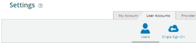
Users—XMS-Cloud Admins
|
1.
|
Click the user button at the upper right of the cloud window and select the Settings option from the drop-down list. Select the User Accounts tab. |
|
2.
|
To create a new user, click +New User. The Set User Details dialog appears on the right. Enter the First Name and Last Name. You can use the optional Additional Details field for notes, comments, etc. Enter the user’s Email address—this will be used as the account’s user name for logging in, as well as for sending email notifications for user accounts. Since the email address is the identifier for this account, it must be unique, i.e., not used for any other user accounts. |
|
3.
|
XMS: this determines user privileges for the account. Admin privileges give read-write access to all of the features in XMS-Cloud. User privileges are similar, except that they cannot use Provider Management or create any of the User Accounts described in this section (these two tabs are not shown to those with User privileges). Read Only privileges allow the user to view information and use features such as Reports, but not save any changes. Some links and buttons that would allow you to make changes are not shown—for example, Save and New Profile buttons are not shown. In the lower field, you may set the slider to Yes to make this user a Guest Ambassador. In this case, the user will only have privileges for Managing Guests. Click Save when done. |
|
4.
|
Accounts with Read Only or User privileges can be restricted to particular parts of the network. (Admin accounts will be automatically changed to User accounts if you restrict them.) By default, these accounts can access the entire network included in each of their Domains. To limit access, set Would you like to restrict this account to specific sections of your network? to Yes. Click the edit button  to specify the sections of the network that this user can view or manage. The Cambium Xirrus devices that can be viewed/managed are specified by selecting one or more Profiles, Access Point Groups or EasyPass portals. All three types can be combined in one account. If you include more than one entry, the account will be able to access any device that is included in any of the entries. All XMS-Cloud displays and reports will restrict information shown to include only the selected portions of the network. For example, only clients connected to accessible APs will be shown, and only rogue devices and alerts related to those APs are shown. If you don’t add any profiles, groups, or portals, the user will not be able to see any part of the network. to specify the sections of the network that this user can view or manage. The Cambium Xirrus devices that can be viewed/managed are specified by selecting one or more Profiles, Access Point Groups or EasyPass portals. All three types can be combined in one account. If you include more than one entry, the account will be able to access any device that is included in any of the entries. All XMS-Cloud displays and reports will restrict information shown to include only the selected portions of the network. For example, only clients connected to accessible APs will be shown, and only rogue devices and alerts related to those APs are shown. If you don’t add any profiles, groups, or portals, the user will not be able to see any part of the network. |
|
n
|
Profiles—allows access to the Cambium Xirrus APs that are profile members. The user can only view the selected profiles, can’t create or delete profiles, and can’t change the assignment of member APs to a profile. For filter drop-down choices, the selected profiles are shown, as well as the SSIDs that are defined in those profiles. |
|
n
|
Groups—allows access to the APs that are group members. The user can’t create, edit, or delete groups. For filter drop-down choices, the selected groups are shown. |
|
n
|
EasyPass—allows access to edit or view the selected EasyPass portals. If no portals are selected, the user will not have permission to view any EasyPass portals. The user can only assign portals to SSIDs that are part of the user's accessible profiles, and cannot create or delete any EasyPass portals. |
|
5.
|
Newly entered users are notified of their accounts at the email addresses that were entered. Emails will include a link for accessing the cloud as well as a temporary password. |
|
6.
|
You may modify user account settings from the User Accounts list. Hover over the desired user and click the Details button . In the Set User Details dialog, make the desired changes. |
|
7.
|
To change additional account settings, such as notification settings and mobile contact, the user must log in to the cloud using the desired account, and make changes as described in My Account. |
XMS-Cloud Single Sign-on (SSO)
This option sets up single sign-on access for XMS-Cloud accounts, if your organization is using Google G-Suite, Microsoft Azure, or an identity provider that uses SAML 2.0. Users will be able to enter the same credentials that they use to log in to the rest of your organization's network and applications. Access credentials are securely exchanged between the ID provider and service platforms such as XMS-Cloud, creating a smooth SSO access across different platforms.
|
1.
|
On the XMS-Cloud Settings page, select the User Accounts tab, then Single Sign-On, and enable SSO. |
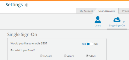
|
2.
|
Select one of these three different identity provider platforms. Only one sign-on method may be defined for each of your Domains. You may locally define Users—XMS-Cloud Admins as well as SSO. |
|
n
|
G-Suite — Click the Follow these steps... link and proceed as directed, similar to the steps in Directory Synchronization for EasyPass Google. XMS-Cloud revokes access to users who have been deleted from the Google directory. To grant access only to users in selected Google Directory Organizations, set that option to Yes, and enter the desired organizations. |
|
n
|
Azure — Authentication is provided by Microsoft Azure. You have the option of installing the Cambium Xirrus EasyPass app or not, just as for client authentication in a portal. See EasyPass Microsoft Azure for details and instructions. Regardless of whether the app is installed starting from this page or from an Azure portal’s General page, the app will be used in both places. When you have completed the setup on the Azure web site, you will be returned to the XMS-Cloud Single Sign-On page. To restrict access to particular groups in Azure, set Would you like to restrict access to specific groups to Yes. Please wait for XMS-Cloud to list the groups defined in the Azure domain— this may take some time. |
|
n
|
SAML (Security Assertion Markup Language)—Enables use of Federated Identity managers that use SAML, such as Okta. See SAML below to set up this option. |
|
3.
|
Select the Default XMS role for new users. This determines user privileges for the account. Admin privileges give read-write access to all of the features in XMS-Cloud. User privileges are similar, except that users cannot use Provider Management or create any of the User Accounts described in this section (these two tabs are not shown to those with User privileges). Read Only privileges allow the user to view information and use features such as Reports, but not save any changes. Some links and buttons that would allow you to make changes are not shown—for example, Read Only users do not see Save and New Profile buttons. |
|
4.
|
At the bottom of the settings, XMS-Cloud will display the Login URL. Copy this URL and provide it to your users for accessing XMS-Cloud. Users must access XMS-Cloud via this link in order to be authenticated by your chosen Identity Provider. |
SAML
This option sets up XMS-Cloud to obtain user authentication from an Identity Provider (IdP) that is using SAML 2.0. The following procedures illustrate how to configure SAML integration for Okta as the IdP.
Integration with Okta Using SAML 2.0
|
1.
|
On the XMS-Cloud Settings page, select the User Accounts tab, then Single Sign-On, and enable SSO. Set the platform to SAML. |
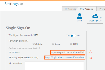
|
2.
|
XMS-Cloud provides the links shown above, which will be needed to enter when you configure your IdP. |
- SP SSO Url, labeled A, is the Service Provider’s (SP—in this case XMS-Cloud) SSO address.
- SP Entity ID (SP Metadata link), labeled B, tells the IdP where to find the metadata information that it needs describing XMS-Cloud.
|
3.
|
Click the link or download the file provided by the SSO service provider to enter in the IdP metadata. |
|
4.
|
Copy and paste all of the text from that link or file into Idp Metadata field as shown below. |
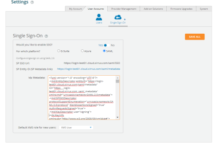
|
5.
|
Select the Default XMS role for new users from the dropdown. |
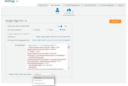
|
6.
|
Click SAVE ALL. and Login Url will be created. |
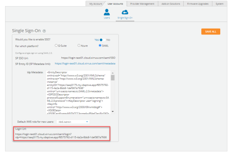
|
7.
|
Provide the Login Url to the SSO user. |
Provider Management
Use this page to select the mobile providers that are available for guest access in each country, or to add carriers if they are not listed. The carriers that you select are then available for guest access, for texting account information to guests, and for texting notifications to users. The selected providers are offered in the Mobile Carrier drop-down list that appears anywhere a mobile number may be entered.
|
1.
|
Click the user button at the upper right of the cloud window and select the Settings option from the drop-down list. Select the Provider Management tab. |
|
2.
|
Page through the provider list to find the desired country. Providers that have a green checkmark  are enabled and are accessible for guests and for notifications. Click on the header of a column to sort the entries by that column. Click the checkmark on the left of an entry to disable or enable that provider. Your changes are automatically saved. Note that when you enter a mobile number for a new guest account or user notification, you will be asked to select a country and select a mobile carrier. After selecting a country, the drop-down list of carriers only displays the providers for that country that have a green checkmark. Selecting providers by using the green checkmark is simply a convenience so that you won’t have to view a list that might have as many as 100 or more carriers to scroll through. are enabled and are accessible for guests and for notifications. Click on the header of a column to sort the entries by that column. Click the checkmark on the left of an entry to disable or enable that provider. Your changes are automatically saved. Note that when you enter a mobile number for a new guest account or user notification, you will be asked to select a country and select a mobile carrier. After selecting a country, the drop-down list of carriers only displays the providers for that country that have a green checkmark. Selecting providers by using the green checkmark is simply a convenience so that you won’t have to view a list that might have as many as 100 or more carriers to scroll through. |
|
3.
|
If your carrier is not shown on the Provider Management page, you may enter it by clicking the Add Custom button. After you enter the Provider and the Email Domain, the SMS Address Format will be shown at the bottom of the form. Some providers require a prefix or suffix to their SMS address: for example, E-Plus in Germany uses the prefix 177 on SMS addresses. Verify that the SMS Address Format is correct, then click Save when your entry is complete. |
Add-on Solutions
If you use services such as Twilio or a technology partner such as AirWatch Mobile Device Management, this area allows you to set up access to the add-on service. For example, you may enter server URLs and account login information here. The information requested is tailored to the particular add-on. Your APs will be configured with the necessary settings to work with the add-on, according to their Profiles.
|
|
Click the user button at the upper right of the cloud window and select the Settings option from the drop-down list. Select the Add-on Solutions tab. |
|
|
Click an add-on name to expand that entry, for example, AirWatch MDM. |
Current add-ons include the following:
AirWatch Mobile Device Management
Most of the AP settings entered in this section are taken from your AirWatch account.
|
1.
|
API URL: Obtain this from your AirWatch service’s System / Advanced / Site URLs page. Copy the REST API URL string into this field. This specifies the AirWatch API that the Access Point will call to determine the enrollment and compliance status of a mobile device attempting to connect to the Access Point. The steps that the user will take enroll a device are described in User Procedure for Wireless Access with AirWatch. |
|
2.
|
API Key: Obtain this from your AirWatch server. Go to the System / Advanced / API / REST page, General tab, and copy the API Key string into this field. The key is required for access to the API. |
|
3.
|
API Username and API Password: Enter the user name and password for your account on the AirWatch server. |
|
4.
|
API Timeout: (seconds) If AirWatch does not respond within this many seconds, the request fails. |
|
5.
|
API Polling Period: (seconds) Mobile device enrollment and compliance status will be checked via polling at this interval. Note that there may thus be a delay before the mobile device will be admitted. |
|
6.
|
API Access Error: Specify whether or not to allow access if AirWatch fails to respond. The default is to Block access. |
|
7.
|
Redirect URL: Obtain this from your AirWatch server. Go to the System / Advanced / Site URLs page, and copy the Enrollment URL string into this field. When a mobile device that is not currently enrolled with AirWatch attempts to connect to the AP, the device displays a page directing the user to install the AirWatch agent and go to the AirWatch enrollment page. Note that Android devices will need another form of network access (i.e. cellular) to download the agent, since un-enrolled devices will not have access to download it via the Access Point. See User Procedure for Wireless Access with AirWatch for more details. |
|
8.
|
Now you must select the Profiles whose member APs will use AirWatch. In the Access Control column on the SSIDs list, select AirWatch for any SSID that will use this add-on for mobile device management. Note that the AirWatch option will grayed out until you configure AirWatch using the steps just described. |
User Procedure for Wireless Access with AirWatch
|
1.
|
A user connects to the wireless network via a mobile device and authenticates in the usual way. As soon as the user browses to an Internet location, the AP asks the user to wait while it checks device enrollment and compliance status by querying the AirWatch API with the device MAC address. |
|
|
NOTE:
Device enrollment and compliance status will be checked via pollings other may be a delay before the device will be allowed in. That delay will depend on the API Polling Period setting.
|
|
2.
|
If AirWatch responds that the device is enrolled and compliant, the device will be allowed into the network. The device will be considered compliant if AirWatch finds that the device does not violate any applicable policies for that device. (If no policies are assigned to the device in AirWatch, then the device is compliant by default.) |
|
3.
|
If the user’s mobile device is not enrolled with AirWatch, all user traffic will be blocked, except that HTTP traffic is redirected to an intermediate page on the Access Point that tells the user to download and install the AirWatch agent. The page displays a link to the AirWatch-provided device enrollment URL. This link is a pass-through that allows the user to go through the enrollment process. The user will need to enter your organization’s AirWatch Group ID and individual account credentials when requested. Once the agent is installed, the user must start again at Step 1. |
|
|
NOTE:
Android devices must go to the PlayStore to install the agent BEFORE they can go through the enrollment process. This mean sun-enrolled devices need another form of network access (i.e., cellular or an unrestricted SSID) to download this agent, as they are not permitted access to the PlayStore.
|
|
4.
|
If the device is enrolled with AirWatch but not compliant with applicable policies, all traffic will be blocked as in Step 3 above, and the HTTP traffic will be redirected to an intermediate page on the Access Point that tells the user which policies are out of compliance. This page contains a button for the user to click when the compliance issues have been corrected. This button causes AirWatch to again check device compliance. The user's browser is redirected to a “wait” page until the Access Point has confirmed compliance with AirWatch. The user’s browser is then redirected to a page announcing that the device is now allowed network access. |
If the Access Point is unable to access AirWatch to obtain enrollment and compliance status (for example, due to bad credentials, timeout, etc.), device access to the network will be granted according to the API Access Error setting (Allow or Block). If this field is set to Block, traffic will be blocked as in Step 3 above and HTTP traffic will be redirected to an informational page that informs the user that AirWatch cannot be contacted at this time and advises the user to contact the network administrator. If this field is set to Allow, then the device will be allowed network access.
Content Filtering
This setting is part of the configuration to use a DNS-based web filtering service— all DNS requests are forwarded to this address. Content filtering protects your network and your users, and enforces organization-wide restrictions on web sites that may be accessed. It is enabled on a per-SSID basis.
Use these steps to set up content filtering:
|
1.
|
Open the Settings > Add-On Solutions tab and click Content Filtering. |
|
2.
|
Enter the IP address (not a host name) for your content filtering server. |
|
3.
|
Go to Profiles and open a profile that will use content filtering. Go to its Policies page. |
|
4.
|
For each SSID that is to use content filtering, create its SSID policy if it doesn’t already exist. Click Show Advanced on the policy, and then turn on Content Filtering. |
|
5.
|
Set up Content Filtering on additional SSID policies or profiles as desired. |
Twilio SMS
XMS-Cloud sends email and SMS text messages for a variety of purposes. For example, it contacts network administrators with notifications about network status. It contacts wireless users with guest registration information. Twilio allows SMS messages to be sent to users via their carriers, worldwide.
Most of the settings entered in this section are taken from your Twilio account.
|
1.
|
Account SID: Obtain this from your Twilio account. |
|
2.
|
Auth Token: Obtain this from your Twilio account. |
|
3.
|
Phone Number: Enter the phone number of your Twilio account. Use Twilio’s international number format: “+”|country code|phone number (+11234567890). |
Once these settings are complete, XMS-Cloud uses Twilio to send all SMS text messages to network administrators and wireless users. Carrier/country information no longer needs to be entered by guests using access portals.
Firmware Upgrades
XMS-Cloud typically upgrades APs to the latest release automatically. There is also a manual upgrade option that lets you control which software releases are running on your network—if your network is running well, you can stay with the current release. Manual upgrades can be used to test a new release on a selected profile. Upgrade methods are described in these sections:
Automatic Upgrades
Set Upgrade Type to Automatic Upgrades to update Cambium Xirrus devices automatically when new software versions are released. You can control when this occurs and what type of software to install.
Configure the following upgrade options:
Firmware Type—Mainline or Technology
XMS-Cloud allows you to choose between two types of software version to deploy on the network:
|
|
Mainline—Mature code with an emphasis on stability, including only time tested functionality and patch releases to fix problems. New functionality from the Technology code base is adopted into Mainline once it has been successful in use over time. Mainline firmware is selected by default. |
|
|
Technology—New features are released first on the Technology platform for early adopters. These builds have passed our quality assurance procedures and have been proven by our beta process. |
When you select one of these two options for a specific domain (see Domains in Command Center), that option applies to all of the APs in the domain. It cannot be overridden for a particular AP or profile. The upgrade to the desired version will occur during your next maintenance window (see Maintenance Window).
If you are an administrator of a Command Center account and you are currently managing the parent (top-level) domain, then the Default Firmware setting applies to all of the domains created afterwards. Changing the Default Firmware setting does not affect existing domains, although you may change each domain’s firmware setting individually.
Note that the newest AP features are only available on Technology builds. Switching from Technology to Mainline firmware may cause newer features to stop working if they are already in use on APs when they are switched to the Mainline build. If a setting for a relatively new feature is grayed out, there will be a star next to it if it requires the Technology option. Click the star to be taken to the Default Firmware setting.
Optimize Upgrade for Speed or Uptime
Deployment of new firmware on the network can be optimized for different preferences. Select one of the following:
|
|
Speed—After downloading their firmware, APs are rebooted to complete the upgrade as quickly as possible. APs will reboot at about the same time, so the wireless network will be unavailable to all clients at that time. If you want to get a patch out to all APs right away, use this option and also see Maintenance Window to set up a near-term time for the upgrade. (Remember to set the schedule back to your normally preferred time after the upgrade is done.) |
|
|
Uptime—Only one AP at a time per profile is rebooted. More time will elapse before all APs are running the upgraded firmware, but downtime for clients will be minimized since most will have network access during the reboot through a nearby AP. You will be notified if the time estimated to complete the upgrade of all network APs exceeds the duration of your scheduled maintenance window for the week (if you have one set—see Maintenance Window, below). |
Maintenance Window
By default, AP firmware upgrades occur at a time determined by Cambium Xirrus. Use this tab if you need to schedule upgrades for a particular maintenance window, or to schedule upgrades to avoid a time when wireless service is mission-critical (for example, schools ensuring that upgrades don’t occur during exam periods).
When you specify a schedule, upgrades are only allowed to commence during that time window. When XMS-Cloud is ready to push a new software version to APs, it obeys your schedule settings, if any. You can set up a daily schedule, or a schedule that applies at the specified time on selected days of the week. Note that XMS-Cloud requires the latest firmware versions for optimal performance and to support the latest features, so please don’t enter an overly restrictive schedule. For example, if you only allow upgrades from 1 AM to 3 AM Monday, then a new software release issued later on a Monday would not make it onto APs until almost a week later.
If you have a Command Center account and you are an administrator currently managing the parent (top-level) domain, then the upgrade schedule applies to all domains that don’t have upgrade schedule settings. Schedules may also be configured for individual domains—they will override parent domain settings.
|
1.
|
To schedule your own upgrade window, select Custom. |
|
2.
|
Every Day/Week: Select Day to specify a daily window of time for upgrades. Select Week to allow upgrades only on certain days of the week (select one or more days in the Days Active field). |
|
3.
|
Specify the time-of-day window for upgrades by selecting a Starting and ending hour. This time period must be at least two hours long. Select the Timezone for the upgrade window. |
Manual Upgrades
The Automatic Upgrades option always updates the wireless network to use the latest software releases. If you do not want to upgrade at this time because your network is running well with your current software, set Upgrade Type to Manual Upgrades. Manual mode lets you specify whether to upgrade or not for each type of firmware (AOS, etc.). You can manage risk by testing a new release on a specified profile and roll back the upgrade if desired. Links for release notes are provided.
The following manual upgrade options are the same as described for automatic upgrades:
The special manual upgrade options are managed separately for each type of Cambium Xirrus firmware. If you have no devices that use a particular type of firmware, it is not listed.
|
|
AOS is used on most APs, except for the two models mentioned below. |
|
|
XR320 is used on the XR-320 only. |
|
|
X2-120 is used on the X2-120 only. |
The upgrade section for each type of firmware shows the same information and offers the same options.
|
1.
|
Current Version shows the release of this firmware running on network devices. |
|
2.
|
Versions Available shows the latest releases that are available, both Technology and Mainline. If one of those versions is already the Current Version, it is not shown. Links to Release Notes are provided, both for the Current Version and all Versions Available. |
|
3.
|
To test a new version of firmware on members of a single profile (rather than deploying to all network devices that use that firmware), click the firmware’s link for Test on a Profile. Select the desired profile. |
|
n
|
The upgrade is applied immediately (within several minutes) by default. You may switch the Maintenance Window to Custom mode to specify a scheduled time, just as for Automatic Upgrades. |
|
n
|
If you’re satisfied with the results of the upgrade test, click Deploy to All Devices. The tested version will be deployed to all Cambium Xirrus devices that use this type of firmware, as scheduled in the Maintenance Window. |
|
4.
|
If you don’t use Test on a Profile, you may click on a release to deploy it to all of the devices in this Domain, as scheduled in the Maintenance Window. |
|
5.
|
Note that some newer Cambium Xirrus device types require a minimum release number to operate. For example, the XH2-240 requires AOS Version 8.5.2 or higher. If you select a release and some devices are only supported by higher release numbers, then those devices will instead be upgraded to the lowest release that supports them. |
System
This tab allows you to configure a data retention policy for user data privacy.
Data Retention
Use this feature to specify how long client data is retained by XMS-Cloud. Select a period of time for keeping client and session data. Data that is older than the specified time period is deleted. By default, data is typically kept for eighteen months or longer, at the discretion of Cambium Xirrus.
This feature can be part of your policy for implementing General Data Protection Regulation (GDPR), the EU regulation on data protection and privacy.
Grant Support Access
This option allows customer support personnel to make changes to settings within your XMS-Cloud account. It is disabled by default, so if you wish to let support personnel modify your settings, you must enable this first.
|
|
To enable support access, click the user button at the upper right of the cloud window and select the Grant Support Access option from the drop-down list. Click Yes, Grant Access in the Change Access dialog. |
|
|
To disable support access, click the user button at the upper right of the cloud window and select the Revoke Support Access option from the drop-down list. Click Yes, Revoke Access in the Change Access dialog. |
When you enable or disable support access, an entry is added to the Audit Trail.
XMS-Cloud 10.4
01/26/2021
 . Enter a unique Name and an optional Description, then click Save. The next steps are to create Users (for Command Center) and then assign Access Points (for Domains).